

What we can offer you

Technik
Individual diversity for everyone!
The range of manufacture in transformer construction is incredibly diverse. Many components and technical variables must be taken into account and regulations must be observed. With the following information we would like to offer you a little help. Please do not hesitate to contact us if you are not sure which solution is suitable for you.
If you cannot find what you are looking for, please do not hesitate to send us your inquiry. We will be happy to get back to you directly and personally.
All transformers are manufactured according to the valid VDE regulations (VDE 0570/ EN 61558 or VDE 0532 / EN 60076). It should be emphasized that the transformers are insulated in layers. This ensures high dielectric strength between the windings and a long service life. The transformers are also nested alternately. In contrast to welded lamination packs, this results in a lower reactive current component and lower no-load losses.
Performance
The power rating refers to the power in VA or kVA which can be taken from the secondary side in continuous operation. Our transformers are designed as follows as standard:
- Insulation class B or F
- Installation altitude up to 1000m above sea level
- 40°C ambient temperature
- cos φ = 1 (resistive load)
Voltage
With three-phase current, it must be ensured that the nominal voltage is the voltage measured between the three outer conductors (concatenated voltage).
Frequency
The transformers listed in this catalogue are designed for a frequency of 50-60 Hz. On request we also manufacture transformers for other frequencies.
Operating mode S1
Unless otherwise indicated, all transformers are designed for continuous operation. This operating mode is designated S1 and corresponds to 100% duty cycle (ED).
Operating mode S3
In many applications the transformers are not operated continuously at nominal load. As a result, the size can be reduced considerably in some cases.
In operating mode S3, a cycle time of 10 minutes is assumed. If the cycle time deviates from this value, this must be taken into account when dimensioning the transformer. A deviating cycle time is indicated on the rating plate in minutes.
Example calculation for short-time load according to operating mode S3:

Duration of play = duration of pause + duration of load
Determination of the type power for short-time operation according to operating mode S3 (NT = type power):


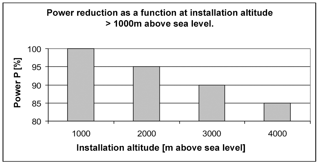
Deviating installation height
The output must be reduced in case of deviating installation heights according to the following diagram.
Deviating ambient temperature
In case of deviating ambient temperatures the power must be reduced according to the following diagram.
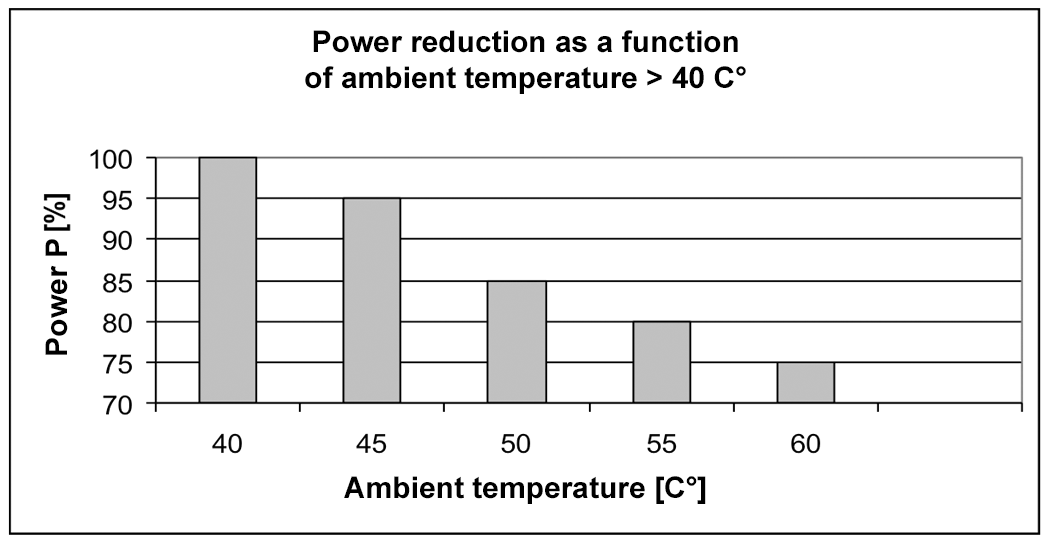
The power must be reduced, because at altitudes of 1000m above sea level and higher ambient temperatures the heat exchange with the environment becomes worse. This means that the transformer would heat up inadmissibly at rated power.
Overload operation of transformers
The overload operation of transformers can be seen in the following diagram.
Temperatures
Under nominal conditions, losses occur in a transformer which generate heat. The resulting excess temperature is linked to certain limit values and is defined within the insulation material classes.
The insulation classes also specify that the hot spot that occurs inside the winding is between class A and class H by 5 to 15 K above the final temperature.
We only manufacture insulation material class H on request.
| Isolation material class | End temperature (continuous temperature - hotspot) |
| A | 100°C |
| E | 115°C |
| B | 120°C |
| F | 140°C |
| H | 165°C |
Short circuit resistance
The transformers listed in this catalogue are not short-circuit-proof according to EN 61558 or short-circuit-proof according to EN 60076-5.
Short-circuit-proof transformer
The short-circuit proof transformer is a transformer in which the temperature does not exceed specified limits if the transformer is overloaded or short-circuited and which continues to meet all requirements of EN 61558 after the overload or short-circuit has been removed.
A distinction is made:
Conditionally short-circuit-proof transformer
- is a transformer equipped with a protective device that opens the input or output circuit or reduces the current in the input or output circuit if the transformer is overloaded or short-circuited.
- Protective devices are, for example, fuses, overload releases, thermal fuses, automatically or not automatically resetting temperature limiters, PTC thermistors and automatically tripping circuit breakers.
Unconditionally short-circuit-proof transformer
short-circuit-proof transformer
- is a transformer without a protective device, in which the temperature does not exceed limit values determined by the design in case of overload or short circuit, and which can continue to operate after the overload or short circuit has been removed
Transformer not short-circuit proof
The non-short circuit proof transformer is a transformer designed to be protected against excessive temperature by a protective device which is not built into the transformer.
Fail-safe transformer
The fail-safe transformer is a transformer which, if not used as intended, will permanently fail due to an interruption of the input circuit, but which does not pose any danger to the user or the environment.
Basic insulation
The basic insulation is the insulation of live parts for basic protection against electric shock.
Additional insulation
The Additional Insulation is an independent insulation in addition to the basic insulation. It protects against electric shock if the basic insulation fails.
Double Insulation
The double insulation consists of basic insulation and additional insulation.
Reinforced insulation
Reinforced insulation is a single insulation of live parts that provides the same protection against electric shock as double insulation under the conditions specified in the relevant standards.
Pollution degree 1 (P1)
None or contamination without influence.
Pollution degree 2 (P2)
No conductive contamination, only occasional conductivity due to condensation.
Pollution degree 3 (P3)
Conductive pollution.
Protective separation
Separation between circuits by basic insulation plus additional additional insulation or protective shielding or by an equivalent protective measure (e.g. reinforced insulation)
Body
For the purposes of EN 61558, a body is a general designation for all touchable metal parts, axles, handles, knobs, levers and the like. Also touchable metal fastening screws and metal foils on touchable insulating surfaces.
Protective screen
Separation of hazardous active parts by means of a conductive shield between them, which has a connection for an external protective conductor.
SELV (safety extra-low voltage)
Voltage of a circuit that is separated from the supply network, e.g. by a safety transformer, and the voltage does not exceed 50 V AC or 120 V smoothed DC.
SELV circuit (formerly safety extra-low voltage)
ELV circuit with protective separation from other circuits, without connections for earthing the circuit or the touchable conductive parts.
PELV circuit (functional extra-low voltage with safe separation)
ELV circuit with protective separation from other circuits, which may be earthed for functional reasons and/or whose touchable conductive parts may be earthed.
Protection class I
The protection against electric shock is not only based on a basic insulation but also on an additional earthing terminal for connection to the protective conductor in fixed installations.
Protection class II
The protection against electric shock is based, in addition to the basic insulation, on a double or reinforced insulation without ground terminal. This makes it independent of the protective measures of the fixed installation. Looped-through protective conductor connections insulated against the transformer are permitted.
Insulation requirements
The table below lists the minimum insulation requirements for the corresponding protective measures.
Minimum insulation requirements
Transformer type | for protective measure | Insulation requirements | Insulation PRI-SEC |
|---|---|---|---|
Autotransformer | no separate winding | no electrical isolation | none |
Power transformer | separate winding | low, no safe isolation | Basic insulation |
Control transformer | Protective earthing | low, no safe isolation | Basic insulation |
Isolating transformer | Protective separation | high, safe isolation | double or reinforced insulation |
Security transformer | Safety extra-low voltage | high, safe isolation | double or reinforced insulation |
We would like to expressly point out that our transformers are all manufactured with double or reinforced insulation to ensure additional safety and a long service life.
Transformers with separate winding
With this type of winding there is no conductive connection between the input and the output winding, they are galvanically isolated. The type power corresponds to the rated power.
Transformers with common winding - economy winding -
With this type of winding there is a conductive connection between the input and output windings. Therefore, the same potential to earth applies to the winding part with the lower voltage as to the winding with the higher voltage.
The restrictions according to VDE 0100 and VDE 0101 must still be observed. Depending on the transmission ratio, considerable material savings can be achieved here.
Protection classes and symbols according to DIN VDE 0711 / EN 60598 / IEC 598
Protection classes | 1st digit: Foreign body protection against | 2nd digit: Water protection against | Pictograms |
|---|---|---|---|
IP 20 | Foreign bodies > 12,5 mm | unprotected |
|
IP 23 | Foreign matter > 12,5 mm | Rain protected with angle of incidence > or - 60° to the vertical | |
IP 40 | Foreign matter >1,0 mm | unprotected | |
IP 43 | Foreign matter > 1,0 mm | Rain protected with angle of incidence > or - 60° to the vertical |
|
IP 44 | Foreign matter >1,0 mm | Splash water from any direction |
|
IP 54 | dust-protected | Splash water from any direction |
|
IP 55 | dust-protected | Jet water from any direction |
|
IP 65 | dustproof | Jet water from any direction |
|
IP 67 | dustproof | waterproof (submersible) |
|


Protection classes and symbols
Schutzklasse/Symbol | Beispiel | |
|---|---|---|
I |
| Connection to the mains protective conductor is mandatory. The symbol is attached to the connection point. |
II |
| The equipment must not have a protective earth connection and must not be connected to the mains protective earth. |
III |
| Equipment for operating with protective low voltage. |


Three-phase transformers
Designation | Pointer Image | Pointer Image | Circuit Diagram | Secondary Starpoint | |
|---|---|---|---|---|---|
Key Figure | Vector Group | OS | US | ||
0 | D d 0 |
|
|
| not available |
0 | Y y 0 |
|
|
| with aprox. 10% loadable |
0 | D z 0 |
|
|
| 100% loadable |
5 | D y 5 |
|
|
| 100% loadable |
5 | Y d 5 |
|
|
| not available |
5 | Y z 5 |
|
|
| 100% loadable |
6 | D d 6 |
|
|
| not available |
6 | Y y 6 |
|
|
| with aprox. 10% loadable |
6 | D z 6 |
|
|
| 100% loadable |
11 | D y 11 |
|
|
| 100% loadable |
11 | Y d 11 |
|
|
| 100% loadable |
11 | Y z 11 |
|
|
| 100% loadable |


In the overview shown, the most important switching groups for three-phase transformers are shown with pointer pattern, ratio, code number and circuit. The winding with the highest voltage in operation is called the high voltage winding and is identified by the number 1 before the terminal designations U, V, W. Accordingly, the winding with the lowest voltage during operation is designated as undervoltage winding and is identified by the number 2 before the terminal designations U, V, W.
The windings can be in delta: D, d in star: Y, y or in zigzag: Z, z, where capital letters stand for the high voltage winding and small letters for the low voltage winding and are designated in this order as the switching group of the three-phase transformer. If the star point is brought out in the respective voltage level, this is indicated by an adjusted N, n. In addition, the subsequent code number indicates the phase shift of the undervoltage compared to the overvoltage of the same name as a multiple of 30°.
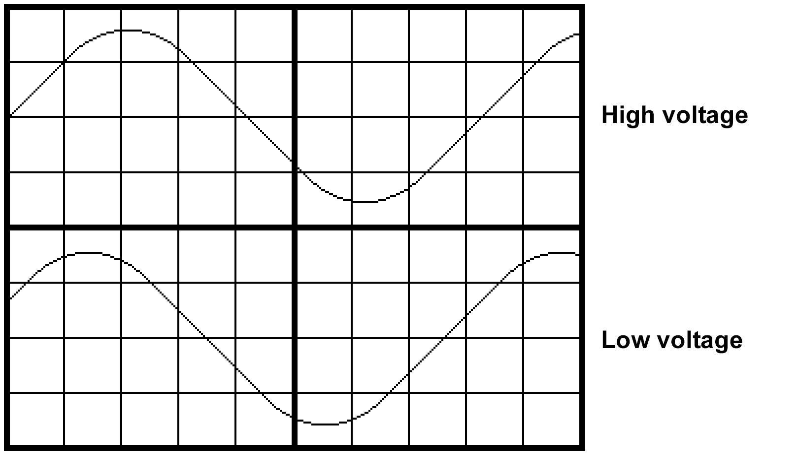
Phase shift of the voltages between the upper and lower side of a three-phase transformer as a function of its characteristic
Key figure: 0
Phase shift: 0°.
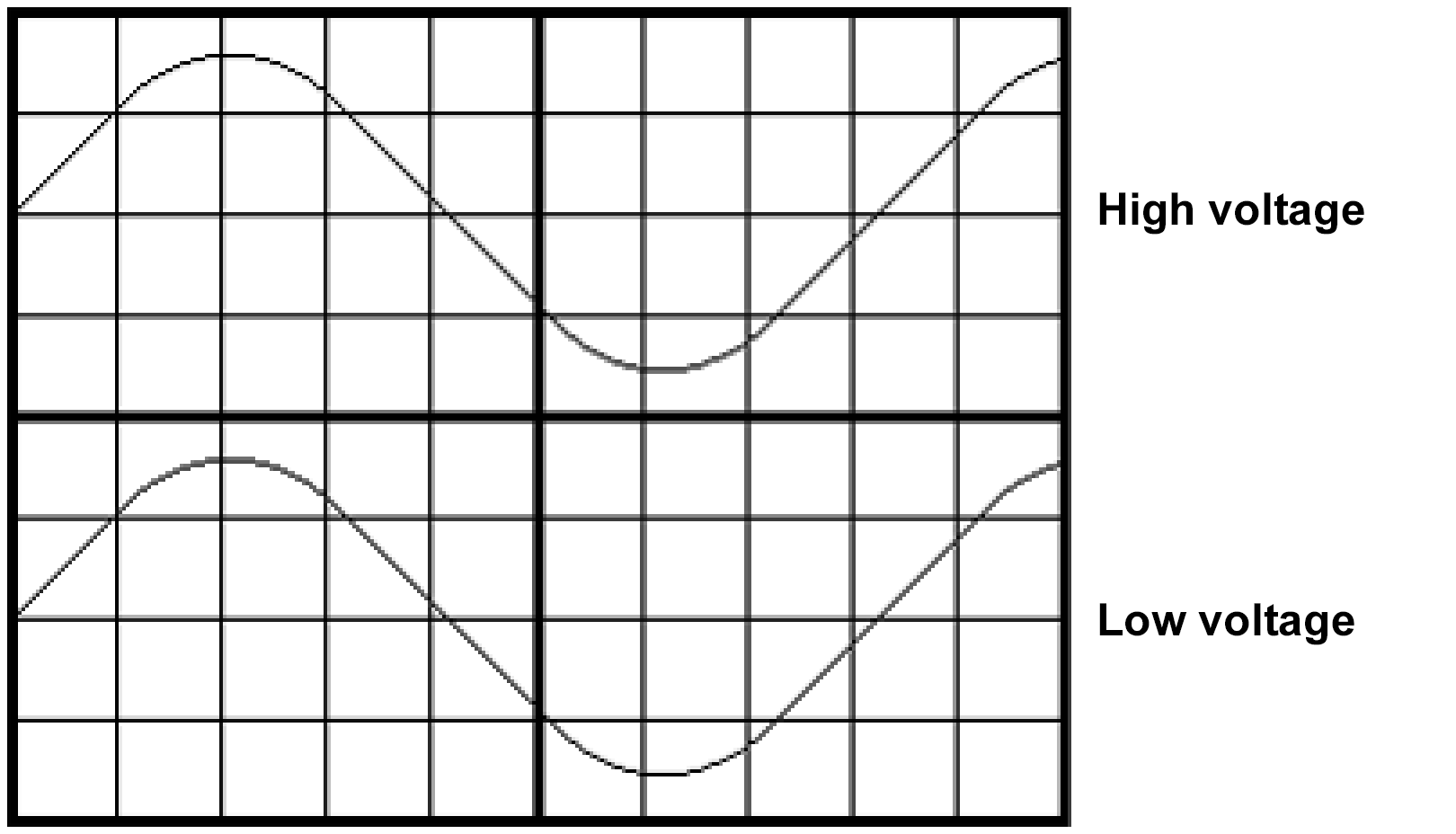
Key figure: 5
Phase shift: 150°
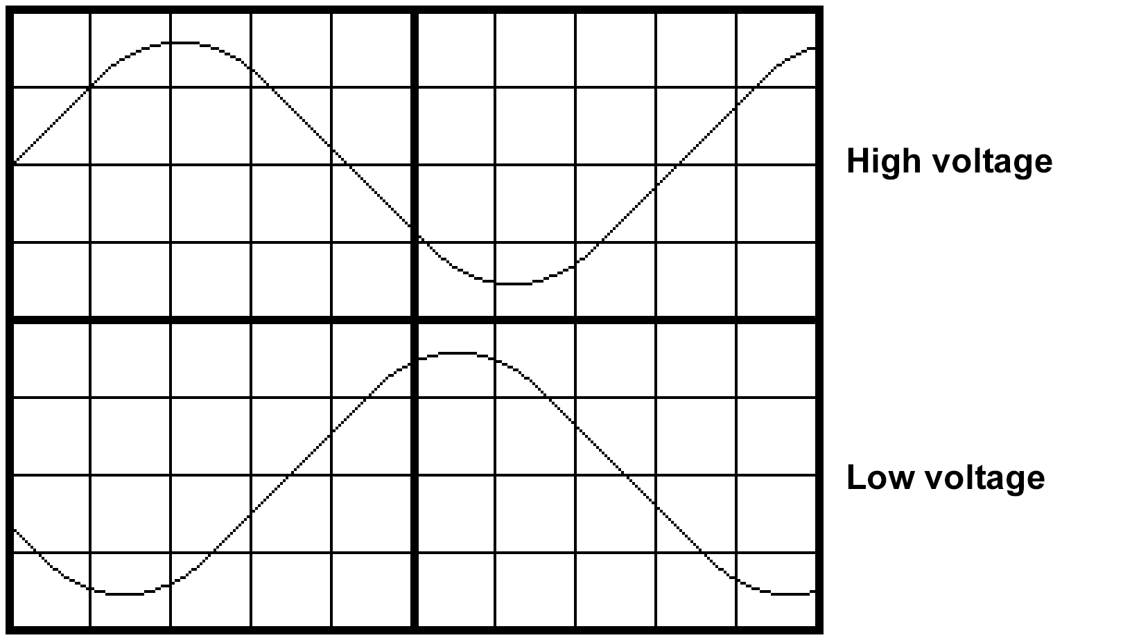
Key figure: 6
Phase shift: 180°
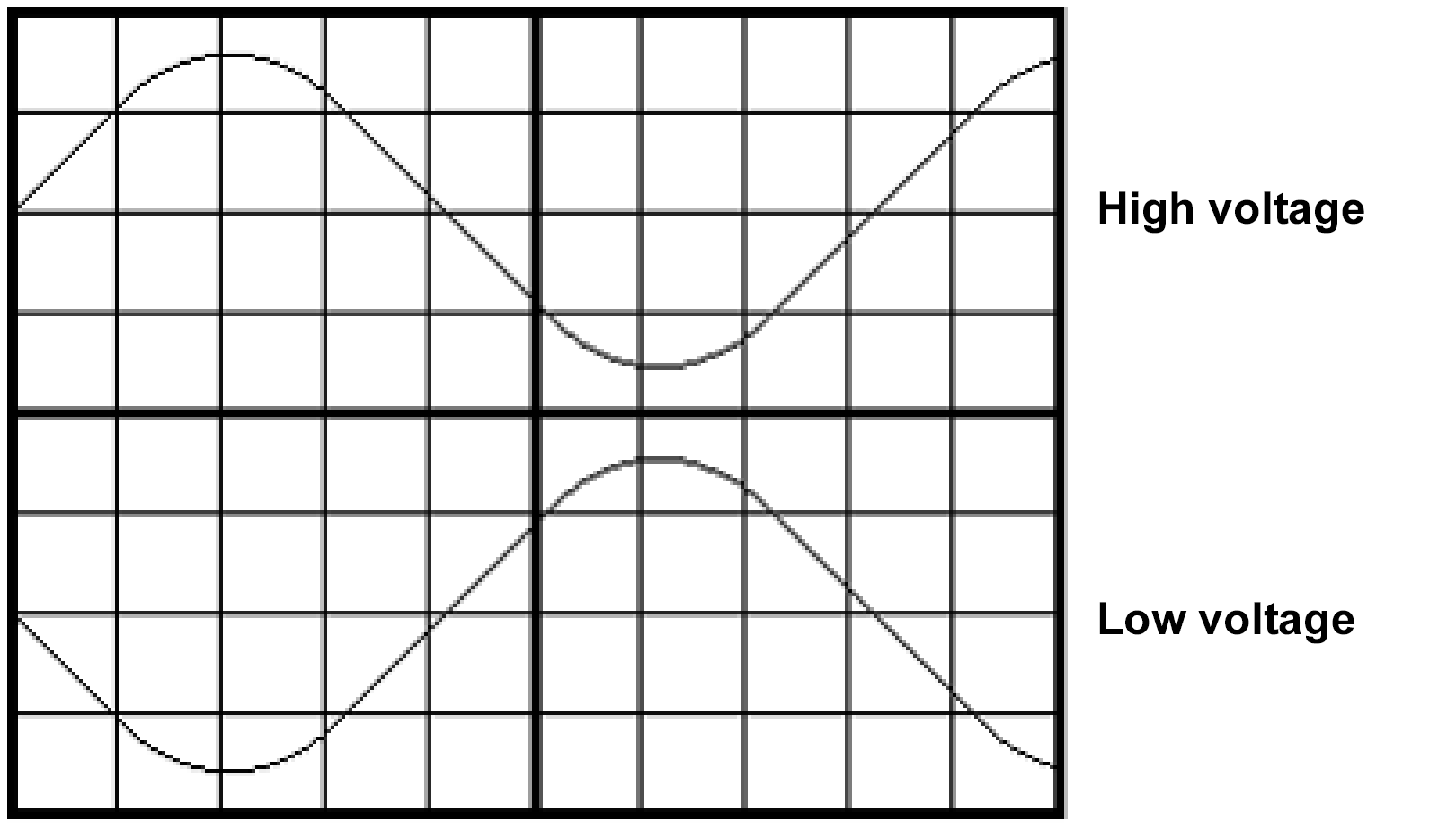
Key figure: 11
Phase shift: 330°
Load capacity of the neutral point
Three-phase transformers are mainly designed in star-star connection Yy0, star-zigzag connection Yz5 or delta-star connection Dy5.
Example star-star circuit with executed star point on the output side Yyn0:
Since the center point of the input side of the transformer is not connected to the star point of the energy source, the star point of the output side may only be permanently loaded with max. 10% of the transformer rated current in consideration of the voltage symmetry.
Example star-star circuit with executed star point on the input and output side YNyn0:
Since the center point of the input side of the transformer is connected to the star point of the energy source, the star point of the output side may be permanently loaded with 100% of the transformer rated current with regard to the voltage symmetry. It is assumed here that the zero impedance of the energy source is sufficiently small when the input-side centre of the transformer is connected to the star point of the energy source.
Example star-zigzag circuit with executed star point on the output side Yzn5:
In star-zigzag connection, the output-side star point of the transformer may be loaded with 100% of the transformer rated current. The zigzag winding must be on the output side. With this circuit, as with the delta connection, an unbalanced load on one phase of the transformer is distributed over all three phases. Each phase winding is half on two different legs of the transformer. With an asymmetrical load, e.g. between 2U - 2V, the symmetrical current component therefore flows through four winding halves, which lie on all three legs of the iron core, of which two winding halves lie on one leg and one winding half on each of the other two legs. Here the load is balanced by the yokes of the core, through which the three limbs are magnetically connected in parallel. An absolutely even load on the individual phases of the input network cannot be achieved by star-zigzag or delta-star connection.
Example delta-star connection with executed star point on the output side Dyn5:
With delta-star connection, the output-side star point of the transformer may be loaded with 100% of the transformer rated current. This circuit is suitable for single-phase loads on the outer conductors of a three-phase transformer with various high currents due to power reductions between the outer conductor and the star point.
The unbalanced load on one phase is distributed over all three phases, because in a delta connection each phase winding is in parallel with the other two phase windings in series. Thus, the compensating currents can occur within the closed circuit of the three windings and cause load balancing on all three windings.
Parallel operation of transformers
If the power of one transformer is no longer sufficient to supply the connected consumers, another transformer must be connected and operated in parallel to the first one.
The following conditions must be met for this parallel connection:
- the same no-load transmission ratio (a percentage deviation of the transmission ratio of up to 1/20 of the relative short-circuit voltage is still permissible - e.g.: uK of a transformer is 10% - its transmission ratio may deviate by 0.5% from that of a transformer running in parallel)
- the same short-circuit voltage (max. 10% permissible deviation)
- same switching group
- rated power difference between the transformers not greater than factor 3
Only if conditions 1 - 3 are met can it be guaranteed that no compensating currents flow during no-load operation and that the currents are correctly divided between the two transformers in terms of percentage under load. Compliance with condition 4. prevents the weaker transformer from being overloaded. In addition, when connecting transformers of different power ratings in parallel, care is taken to ensure that the short-circuit voltage of the weaker transformer is the greater.
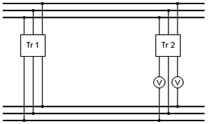
To check the correctness of the parallel connection of two three-phase transformers (to ensure that the phase position of the secondary voltages of both transformers match), the lower circuit can be used. The voltmeters must not indicate any voltage. If this is the case, Tr 2 can safely be connected to TR 1 on the secondary side with three poles.
The short-circuit voltage UK is the voltage that must be applied on the primary side of a transformer short-circuited on the secondary side so that the respective rated current flows in both the primary and secondary winding.
The relative short-circuit voltage uK is the ratio of the short-circuit voltage UK to the primary rated voltage U1N multiplied by 100 in percent:
uK = UK/U1N*100%
UK and U1N are the effective values of the conductor-to-conductor voltages between the terminals of the transformer.
Checking the phase position
Homepage and orders
Our homepage represents a rough cutout of our diverse manufacturing and product range. Please note our continuous updates, which result from the ongoing development of our products, so that you always have the latest information.
For your orders we have created various questionnaires on which you can enter your requirements and wishes. On the basis of these points, we can dimension the transformer you are interested in accordingly and prepare a corresponding offer. You can find the forms for this here.