What we can offer you

Dynamic
Products on the line
Our range of product is various and dynamic. Please do not hesitate to contact us with your specifications in case you do not find what you are looking for. We will be pleased to respond immediately and personally to discuss your wishes.
Do you need additional technical information before you can concentrate on a specific product? We have compiled further information for you on the page Technology.
Our selection of tranformers for you
A basic overview with a short explanation.
Control Transformers
Power Transformers
Isolating Transformers
Safety Transformers
Autotransformers

Ferrite Transformers
Control transformers (VDE 0570 / EN 61558-2-1)
Control transformers have galvanically separate windings. Input circuits and output circuits are separated by at least one basic insulation, so that the transformers can be used in all such places where no double or reinforced insulation is required by installation -or device regulations.
Not only can control transformers adapt the voltage requirements of different electricity circuits, more importantly they can be adapted to different technical requirements.
The correspondingly higher current at low output voltage can, for example, be used for heating purposes or even to separate fusible material. It is also common practice to control the speed of motors by adapting the motor voltage and thus to the various operating points of the driven unit such as fans, pumps and the like.
Not to forget the control of illuminants also by adjusting the supply voltage. The equipment to be maintained in industrial applications often requires low voltages of up to 50Vrms.
Such voltages supplied by a mains transformer are considered functional extra-low voltages for which the protection requirements of isolating and safety transformers according to EN 61558-2-4 and EN 61558-2-6 are not valid.
Scope of application
Fixed or variable 1~ or n~ dry-type mains transformers for circuits without specified double or reinforced insulation with:
U1n ≤ 1000 V
Sn ≤ ∞
fn ≤ 500 Hz
- U1n ≤ 1000 V
- Sn ≤ 1 kVA 1~
- Sn ≤ 5 kVA n~
- für Sn ≤ 40 kVA (special mains transformer, agreement supplier/ customer necessary)
- fn ≤ 500 Hz
The protective insulation may be taken over (or completed) by parts of the device, such as the body. Parts of the output circuits may be connected to the input circuit or to the protective conductor.
Control transformer (VDE 0570 / EN 61558-2-2)
According to EN 61558-2-2, control transformers are used between circuits for which no double or reinforced insulation is specified in installation regulations or equipment regulations. They are used to supply contactors, signalling devices etc. in control circuits. Their design with separate input and output windings provides galvanic isolation of both circuits with a basic insulation that takes into account the expected voltage peaks.
In order to ensure safe operation during switching operations of the inductive loads, two characteristic performance data are particularly important for dimensioning and selecting suitable control transformers:
- Short-time power (switch-on power), is the maximum power output in short-time operation with mixed inductive load (cos φ=0.5), whereby the output terminal voltage that is produced must not fall below 95% of the rated voltage.
- Rated thermal power (holding power), is the maximum power output in continuous operation under purely active load (cos φ=1). The output terminal voltage may not deviate from its rated value by more than ± 5%.
In principle, the voltage rise between thermal rated power and no-load must not exceed 10% of the load voltage.
Scope of application
Fixed or variable 1~ or n~ dry control transformers for circuits without specified double or reinforced insulation with:
- U1n ≤ 1000 V
- Sn ≤ ∞
- fn ≤ 500 Hz
The protective insulation may be taken over (or completed) by parts of the device, such as the body. Parts of the output circuits may be connected to the input circuit or to the protective conductor.
Isolating Transformer (VDE 0570 / EN 61558-2-4)
The isolating transformer is a transformer that must be used wherever there are increased requirements such as double or reinforced insulation between the input and output circuits.
Field of application
Fixed or variable 1~ or n~ dry isolating transformers with:
- U1n ≤ 1000 V
- Sn ≤ 25 kVA, 1~transformers
Sn > 25 kVA (special transformer, agreement supplier/ customer necessary) - Sn ≤ 40 kVA, n~transformers
Sn > 40 kVA (special transformer, agreement supplier/ customer necessary) - 50 Veff AC < U20 or U2n ≤ 500 V AC
according to national regulations and other special applications:
U20 or U2n ≤ 1000 V AC - 120 V DC < U20 or U2n ≤ 708 V DC (smoothed)
according to national regulations and other special applications:
U20 or U2n ≤ 1415 V DC (smoothed) - fn ≤ 500 Hz
Field of application
Wherever the protective measure "protective separation" is required.
Safety Isolating Transformer (VDE 0570 / EN 61558-2-6)
The safety isolating transformer must be used wherever there are increased requirements such as double or reinforced insulation between the input and output circuits.
Field of application
Fixed or mobile 1~ or n~ dry safety transformers with:
- U1n ≤ 1000 V
- Sn ≤ 10 kVA, 1~Transformers
- Sn ≤ 16 kVA, n~Transformers
- U20 ≤ 50 V AC
- U20 ≤ 120 V DC smoothed
- fn ≤ 500 Hz
Field of application
With a safety transformer, for example, a SELV circuit can be implemented.
Autotransformer (VDE 0570 / EN 61558-2-13 Auto transformers (VDE 0570 / EN 61558-2-13 )
Autotransformers are transformers that are suitable for all applications where
no electrical isolation between the input and output circuits is required, can be used.
Fixed or variable 1~ or n~ dry-type autotransformers (instrument transformers or independent transformers) for circuits without specified intermediate insulation with:
- U1n ≤ 1000 V
- Sn ≤ 20 kVA 1~, (Core power ≤ 1 kVA)
- Sn ≤ 100 kVA n~, (Core power ≤ 5 kVA)
(Core power ≤ 40 kVA: special autotransformer with Sn = ∞) - U2n and U20 ≤ 1000 V AC u. 1415 V DC smoothed
applies to independent autotransformers: U20 ≥ 50 V u. 120 V DC smoothed
Notes
Additional requirements may apply:
- for on-board operation on ships and aircraft
- for tropical use
- for special environmental conditions
Application
e.g. as upstream transformer, if the mains voltage differs from the mains voltage of the consumer.
With this type of winding there is a conductive connection between the input and output windings. Therefore, the same potential to earth applies to the winding section with the lower voltage as to the winding with the higher voltage.
The restrictions according to VDE 0100 and VDE 0101 must still be observed.
Depending on the transmission ratio, considerable material savings can be achieved here. The type power is always lower than the rated power.
Example:
Input voltage: 460 V
Output voltage: 230 V
Nominal power: 1000 VA

Type output = Nominal power* (1- Under voltage/ High voltage)
This means that a transformer can be used whose type output is only 500 VA.
Ferrit-Transformatoren Ferrite transformers
Transformers for switching power supplies:
Switch Mode Power Supply (SMP) transformers are used more and more frequently today. The winding parts required for these differ considerably from those in conventional power supplies. The inductive components are designed for a much higher frequency (25 to 300 kHz). In addition, depending on the operating principle, several winding parts are required in addition to the transformer, such as interference suppression chokes, power factor chokes and storage chokes.

Bildtitel
Schematic diagram of a switching power supply with the inductive components
All switching power supplies have basically the same principle of operation: The voltage coming from the mains is rectified, or a DC voltage is already available. This voltage is chopped with a correspondingly high frequency by a semiconductor switch, which is controlled by an electronic circuit. The resulting pulses are translated to the desired output voltage via a choke or a transformer and then output as DC voltage via a rectifier, a storage choke and a charging capacitor. If the power is supplied from the mains, a power factor choke converter must be connected upstream in accordance with EN61000-3-2 from a power consumption of 75W, so that the current drawn from the mains remains sinusoidal (cos φ ≈ 1). The control electronics can now be designed in such a way that the output voltage is regulated via the duty cycle. The voltage is then load-independent and the power supply unit is short-circuit-proof.
There are various different types of switching power supply circuits. Basically one differentiates between blocking, flow and resonance converters. Flyback converters are usually all choke converters and converters with a transformer, in which the individual windings are to be regarded as storage chokes. For this reason the transmission ratio of a flyback transformer is not equal to the voltage transmission ratio. In the conducting phase of the switching transistor, the core is magnetised via the primary winding. In the blocking phase of the switching transistor, the magnetic energy of the core is transferred to the output via the secondary winding. In flux converters, as the name suggests, the input voltage is directly transferred in the flux phase of the switching transistor in the ratio of the number of turns and delivered to the output.
The resonance converter is a special case of the flux converter. It uses an oscillating circuit and regulates the output voltage not by the duty cycle but by a change in frequency. The advantage is that the switching transistors can be switched in the current zero crossing.
The most common switching types are described below with their advantages and disadvantages. Depending on the application, you can now select the most favourable switching type. Basic criteria are e.g. power, galvanic separation, interference suppression, effort, price and size.
Overview of the switching types:
Further information on the individual circuit types with circuit diagrams:
Down Converter

Advantages:
- Short circuit and open circuit resistance
- Easily realizable.
- Low switching effort.
Disadvantages:
- No galvanic isolation.
- Control must float.
Application:
- In places where longitudinal regulators cause high losses.
Aufwärtswandler Up-converter

Advantages:
- Little effort needed to generate high voltages.
- Control is connected to ground
Disadvantages:
- No galvanic isolation.
Application:
- Battery devices, such as photo flash, mobile phones.
Inverting Converter

Advantages:
- Short circuit and open circuit resistance
- Easily manufactured
- Low switching effort
Disadvantages:
- No galvanic insulation.
- Controls must float
- not idle-proof in unregulated operation
Application:
- In places where an non galvanically isolated inverse voltage is required.
Flyback Transformer

Advantages:
- Little manufacturing effort requried.
- multiple regulated output voltages.
- Power up to approx. 300W.
- Wide regulation range (for iwde range power supplies without voltage switching).
Disadvantages:
- Uds of the transistor ≥ 2 Ue.
- Good magnetic coupling.
- Requires a large core with air gap.
Single-cycle Flow Converter

Advantages:
- Galvanically isolated and regulated output voltage.
- Power up to approx. 300W.
Disadvantages:
- Uds of the transistor ≥ 2 - Ue.
- Good magnetic coupling.
- Demagnetization winding.
- Storage choke necessary.
Half-bridge Flow Converter

Advantages:
- An electrically isolated and regulated output voltage.
- Power up to the kW range
- Udsof the transistor = Ue
Disadvantages
- Good magnetic coupling.
- Complex control of the switching transistors, driver transformer necessary.
Half-bridge push-pull Converter

Advantages:
- One galvanically isolated and regulated output voltage.
- Power range up to the kW range.
- Uds of the transistor = Ue
- No particularly good magnetic coupling necessary.
- self-balancing.
Disadvantages:
- Complex control of the switching transistors, driver transformer necessary.
Full bridge push-pull Converter

Advantages:
- One galvanically isolated and regulated output voltage.
- Power up to many kW.
- Uds of the transistos = Ue
- No particularly good magnetic coupling necessary.
Disadvantages:
- Complex control of the switching transistors.
- Driver transformer necessary.
- Switching times must be symmetrical.
Push-pull Converter with parallel supply

Advantages:
- One galvanically isolated and regulated output voltage
- Power up to several 100W
- Uds of the transistor = 2 • Ue.
- Simple control, transistors are connected to ground.
Disadvantages:
- No very good magnetic coupling necessary.
- Switching times must be symmetrical.
Push-pull resonant Converter

Advantages:
- An electrically isolated and regulated output voltage.
- Power up to many kW.
- Uds of the transistor = Ue.
- No particularly good magnetic coupling necessary.
Disadvantages:
- Complex control of the switching transistors, driver transformer necessary.
- In the partial load range the frequency can reach the audible range.
Full bridge push-pull Converter
Advantages:
- One galvanically isolated and regulated output voltage
- Power up to many kW
- Uds of the transistor = Ue
- No particularly good magnetic coupling necessary.
Disadvantages:
- Complex control of the switching transistors.
- Driver transformer necessary.
- Switching times must be symmetrical.
Push-pull Converter with parallel supply
Advantages:
- One galvanically isolated and regulated output voltage
- Power up to several 100W
- Uds of the transistor = 2 • Ue.
- Simple control, transistors are connected to ground.
Disadvantages:
- no very good magnetic coupling necessary.
- Switching times must be symmetrical.
Electrical safety:
The necessary clearance and creepage distances, which are required by VDE and EN standards, must be observed! The values that come into consideration here depend primarily on the application, the operating mode and the protection class. A further criterion is the degree of pollution. Depending on the degree of contamination, from open construction to vacuum impregnation to vacuum potting, the clearance and creepage distance can be reduced according to the standard tables.
A special case is the type-tested and monitored production of transformers. Here, for example, the creepage distances can be extremely reduced in vacuum potting. A prerequisite for this, however, is a type test at an approved testing institute. For this purpose, test samples must be prepared and submitted for extensive testing. This type test is only worthwhile for corresponding series sizes. We can, of course, organise test samples and the organisation of the type test at a test institute.
There are various measures to meet these requirements. Here are the most common measures in broad outline:

Advantage:
- The coupling of the windings is utilized optimally .
Disadvantage:
- Elaborate manufacturing required, all rejectors must insulated, otherwise they would be capable of bridging the creepage distances.

Advantage:
- Less work needed, if necessary the leads can be led out without additional insulation.
Disadvantage:
- The coupling of the windings has lesser strengh.

Advantage:
- Coupling is improved even with alternatedly set strips
Disadvantage:
- Greater manufacturing effort required, one more full winding is needed.
Impregnation and casting of transformers:
In principle, these measures contribute to electrical safety. Especially in the vacuum process, the windings are secured against slipping. Smaller cavities, such as the feathering as well as unevenness in the edge strips etc., are filled by the impregnating agent. In addition, the penetration of air humidity is prevented. For the different types of impregnation or grouting, different degrees of contamination are specified in the tables for the creepage distances. This allows the creepage distances in the transformers to be reduced. See previous section 'Electrical safety'.
The following options are used:
- Without impregnation. Inexpensive, for simple applications.
- Air lacquer, dries at room temperature by solvent evaporation.
Also an inexpensive option, but only provides some surface protection. - Two-component impregnating varnish, dip impregnation with oven curing.
Good surface protection, but paint does not penetrate the windings. - Two-component impregnating varnish, vacuum impregnation with oven curing.
Optimum protection, varnish penetrates into the hollow spaces. - Casting with two-component compound in cup.
Inexpensive casting, applicable everywhere where no smaller creepage distances have to be achieved by potting, e.g. toroidal chokes. - Casting with two-component compound under vacuum in the cup.
Optimum casting. The components are cast directly in a vacuum so that almost no air pockets are formed. For type testing (see previous section 'Electrical Safety') the distances in the winding can be reduced to a few mm.
Casting cups:
Casting cups are available for many types. The problem with casting cups is close fitting of cup and coil body. Smallest deviations in shape and dimensions can lead to the fact that a cup of the manufacturer X does not match a bobbin of the manufacturer Y. The coilformer manufacturers have the matching cups available for their coilformers. The variety of manufacturer-specific finenesses, especially for the E-types, must be taken into account. Only the casting cups for the horizontal ETD coilformers up to ETD49 are readily available. Please ask us if you require a specific cup! We almost always have the following type of potting cups in stock:
E13 lg / E16 st / E20 lg and st / E25 lg and st / EC35 / ETD 29 to ETD49 / LP22/13 / LP32/13 and some special types like RM 4 / RM 6 / RM 8 / RM 12 / and some toroidal cores.
For many other types cups are available on request.
UL- Isolationssystem für Ferrittransformatoren: UL insulation system for ferrite transformers:
For exportation to other countries, especially North America, it is advantageous to use components that have UL approval. On request we manufacture our transformers according to our insulation system UL- File No. E193383 up to a temperature range of 155°C. This provides important prerequisites for export, such as UL approval of the complete device in which the transformer is installed.
Transferable power of ferrites:
The maximum transmittable power of ferrite transformers depends mainly on the following factors:
- Frame size
- Operating mode of the switching power supply unit
- Operating frequency
- Fill factor of copper
- Ambient temperature
- Ventilation or cooling
The size is the main factor for the transmittable power. The larger the ferrite core, the more copper can be applied. Due to the larger magnetic cross-section, the number of windings is reduced for the same induction.
Depending on the selected operating mode the ferrite core will be utilized more or less (see table of transmissible power). Which operating mode is selected depends mainly on the application and the required power. (See Switched-mode power supplies overview).
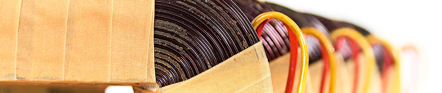
The higher the operating frequency, the greater the transmittable power. As the frequency increases, the induction decreases, the number of windings can be reduced and more copper is applied. The losses in the semiconductors have a disadvantageous effect here, as the switching losses increase at higher frequencies. Depending on the available semiconductor types and the type of switching power supply, a compromise must be sought here. In addition, at higher frequencies the current displacement (skin effect) in the conductor must be taken into account. This means applying several conductors insulated from each other with a smaller cross-section in parallel. HF-stranded wire or thin copper foils are then used for the winding. This results in a worse filling factor, which reduces the transmittable power. See also the following illustrations of the winding structures.
The fill factor of the copper winding indicates the difference between the winding cross-section present in the coil former and the actual copper cross-section that can be applied in practice. In practice, this value is ideally 0.7 or a much smaller value. The decisive factor here is how the actual winding is constructed.
See the following sketches:

With round wire, cavities will inevitably occur during winding. These are not filled with copper . The smaller the diameter of the individual wires (HF wire), the more usable surface area is lost through the gaps.

One way to improve the fill factor even at higher frequencies is to use copper foils. Less space is lost in the process. However, this is only beneficial at low numbers of turns and higher currents. With very thin foils, too much of the intermediate insulation is lost.

A further improvement of the fill factor is the use of profile wires, but this is usually not an option at higher frequencies due to the skin effect.

Additionally, the safety distance required by VDE must be maintained, when disconnecting from the mains. Due to the corresponding edge strips additional surface area for the copper is lost here. Smaller creepage distances can be achieved by casting in a vacuum (see Safety of ferrite transformers).
Table of transmittable power of ferrite cores
The specifications in the table on the next page refer to a fill factor of 0.4 but without margin strips. Furthermore, only the pure copper losses with direct current are taken into account. With high frequency, the losses due to the skin effect and the proximity effect must be added. The values in the table are therefore only to be regarded as reference values, since the winding design, will have considerable effect on fill factors and will result in additional losses . Thermal resistance is also an important factor as well as the maximum ambient temperature. Therefore the ventilation at the location where the transformer is installed plays a major role here. In practice it has been found that for safety transformers with corresponding creepage distances depending on the size, the table values given must be reduced as follows for the reasons given above:
For smaller types up to ETD29 by a factor of 0.3 to 0.5; for larger types from ETD34 on by a factor of 0.5 to 0.8.
Theoretically transferable power of ferrite cores
TYPE | Flyback converter | Single-ended flux converter | Push-Pull Flux Converter | Core Specific Information | ||||
|---|---|---|---|---|---|---|---|---|
25 kHz | 100 kHz | 25 kHz | 100 kHz | 25 kHz | 100 kHz | Weight | RTH | |
E13/4 | 3.1 | 17.4 | 3.6 | 19.9 | 5.0 | 28.0 | 7.2 | 94 |
E16/5 | 8.1 | 41.5 | 9.2 | 47.6 | 13.0 | 67.0 | 13.5 | 76 |
E20/6 | 16.1 | 73.2 | 18.5 | 83.8 | 26.0 | 118.0 | 22.5 | 50 |
E25/7 | 30.4 | 135.2 | 34.8 | 154.8 | 49.0 | 218.0 | 41.0 | 40 |
E30/7 | 58.3 | 259.2 | 66.7 | 296.8 | 94.0 | 418.0 | 47.0 | 23 |
E32/9 | 73.2 | 325.5 | 83.8 | 372.8 | 118.0 | 525.0 | 88.0 | 22 |
E40/15 | 132.7 | 590.2 | 151.9 | 675.9 | 214.0 | 952.0 | 167.0 | 20 |
E55/21 | 333.6 | 1485.5 | 382.0 | 1701.2 | 538.0 | 2396.0 | 340.0 | 11 |
EC35 | 89.9 | 103.0 | 145.0 | 80.0 | 18 | |||
EC41 | 136.4 | 156.2 | 220.0 | 107.0 | 15 | |||
EFD15 | 26.0 | 0.0 | 29.8 | 42.0 | 10.0 | 75 | ||
EFD20 | 71.3 | 0.0 | 81.7 | 115.0 | 19.5 | 45 | ||
EFD25 | 151.9 | 0.0 | 174.0 | 245.0 | 35.0 | 30 | ||
EFD30 | 197.8 | 0.0 | 226.5 | 319.0 | 47.0 | 25 | ||
ETD29 | 59.5 | 265.4 | 68.2 | 303.9 | 96.0 | 428.0 | 71.0 | 28 |
ETD34 | 93.6 | 417.9 | 107.2 | 478.5 | 151.0 | 674.0 | 94.0 | 20 |
ETD39 | 142.6 | 634.3 | 163.3 | 726.3 | 230.0 | 1023.0 | 139.0 | 16 |
ETD44 | 237.5 | 1059.0 | 271.9 | 1212.7 | 383.0 | 1708.0 | 187.5 | 11 |
ETD49 | 368.3 | 1639.9 | 421.7 | 1878.0 | 594.0 | 2645.0 | 244.0 | 8 |
ETD54 | 556.1 | 2478.8 | 636.9 | 2838.6 | 897.0 | 3998.0 | 320.0 | 6 |
ETD59 | 931.2 | 4149.0 | 1066.4 | 4751.3 | 1502.0 | 6692.0 | 422.5 | 4 |
PM50/39 | 242.4 | 1080.0 | 277.6 | 1236.8 | 391.0 | 1742.0 | 208.5 | 15 |
PM62/49 | 417.3 | 1860.0 | 477.8 | 2130.0 | 673.0 | 3000.0 | 400.0 | 12 |
PM74/59 | 700.6 | 3121.7 | 802.3 | 3574.9 | 1130.0 | 5035.0 | 656.5 | 10 |
PM87/70 | 970.3 | 1111.2 | 1565.0 | 1062.0 | 8 | |||
PM114/70 | 1837.1 | 2103.7 | 2963.0 | 2416.0 | 6 | |||
LP23/08 | 29.8 | 34.1 | 48.0 | 23.8 | 41 | |||
LP22/13 | 70.1 | 80.2 | 113.0 | 40.5 | 30 | |||
LP32/13 | 101.1 | 115.7 | 163.0 | 62.8 | 30 | |||
PQ20/20 | 42.2 | 48.3 | 68.0 | 32.0 | 43 | |||
PQ26/25 | 96.7 | 110.8 | 156.0 | 58.3 | 24 | |||
PQ32/30 | 193.4 | 221.5 | 312.0 | 99.2 | 19 | |||
PQ35/35 | 256.1 | 293.2 | 413.0 | 144.2 | 17 | |||
PQ40/40 | 365.2 | 418.2 | 589.0 | 207.0 | 12 | |||
PQ50/50 | 649.1 | 743.4 | 1047.0 | 338.7 | 9 | |||
RM 4 | 14.9 | 17.0 | 24.0 | 5.4 | 120 | |||
RM 5 | 29.8 | 34.1 | 48.0 | 7.5 | 100 | |||
RM 6 | 49.0 | 56.1 | 79.0 | 11.8 | 80 | |||
RM 7 | 66.3 | 76.0 | 107.0 | 17.2 | 68 | |||
RM 8 | 100.4 | 115.0 | 162.0 | 25.3 | 57 | |||
RM10 | 179.2 | 205.2 | 289.0 | 40.5 | 40 | |||
RM12 | 385.6 | 441.6 | 622.0 | 76.5 | 25 | |||
RM14 | 648.5 | 742.7 | 1046.0 | 119.5 | 18 | |||
Calculation of ferrite transformers:
We will be pleased to assist you in calculating the inductive components for a special application. If you send us a completed questionnaire (at the end of this chapter), we will be pleased to produce a complete set of samples for you.
We will also be pleased to help you in the further development phases and provide you with the greatest possible technical support so that you can successfully carry out the development of your project up to series production readiness. Especially when it comes to high voltage or high current applications, there are special problems which we can help to solve.
Manufacturing:
Winding:
Apart from chokes and transformers, especially for switch mode power supplies, we also manufacture any other type of winding material, such as signal transformers, pulse and high current transformers with copper strip windings, symmetry and compensation coils, disembodied coils with self-bonding enamelled wire or self-supporting. We not only wind all standard coilformers, but also manufacture special coilformers in smaller quantities in special cases, if necessary. Please ask us! Winding is carried out on modern computer-controlled winding machines, whose winding programs are created and optimised centrally.
Impregnation and casting:
We use all the processes described in the section "Saturation Impregnation and casting of transformers". Impregnation and casting under vacuum takes place under "real" conditions: After drying, the winding materials are evacuated in a vacuum chamber. Under this vacuum atmosphere, impregnation or casting is then carried out. Subsequently placed in a normal atmosphere the impregnating or casting agent penetrates into the previously evacuated cavities. This process ensures maximum penetration of the mass.
Final check:
Each manufactured winding part is, if necessary or desired, individually tested for all electrical values on a likewise computer-controlled test station. In addition to the transformation ratio, inductance and high voltage test, this also includes winding resistance, Q-factor, leakage inductance, winding capacity, insulation resistance, layer insulation test by means of surge voltage test as well as pre-calibration with adjustable inductances.
Our construction types in detail
Please first select the type of transformer you require

1-phase

1-phase control transformer

1-/2-phase

1-/2-phase in housing

3-phase

3-phase in housing

Ferrite
- Manufactured according to VDE 0570 / EN 61558 ff. or VDE 0532 / EN 60726
- Galvanically isolated windings
- Insulation class T 40/B
- Vacuum impregnation of the windings
- Protection class IP00, prepared for protection class I
- Mounting position any
- Taps ±5% for voltage adjustment
- Input voltages selectable from 200 - 600 V
- Output voltages selectable from 200 - 600 V
- Rated frequency 50 - 60 Hz
- Connections with screw terminals or terminal lugs
- PE connection to earthing bracket or terminal
- Mounting on mounting brackets
Options
- Manufacturing according to UL 506 with type approval according to UL-File E306982
- Production according to a UL insulation system of insulation class F
- Production according to Germanischer Lloyd (gL)
- Design for primary-side thyristor control
- Temperature switches, temperature fuses, fuse terminals
- Deviating input and output voltages
- Winding taps
- Additional windings
- Shield winding
- Terminal arrangement
- Deviating degrees of protection
Sketch *TE for max. rated current of 25A:

Sketch *TE for rated current of 25 - 40A:

Sketch *TE for a rated current above 40A:

Measurements and weights *TE
Type | Rated Power | A | B | C1 | C2 | D | E | F1 | F2 | G | Cu-Weight | Total-Weight |
|---|---|---|---|---|---|---|---|---|---|---|---|---|
mm | mm | mm | mm | mm | mm | mm | mm | mm | aprox. kg | aprox. kg | ||
*TE-25 | 25 | 66 | 53 | 78 | 50 | 40 | 33 | 4,8x9 | 0.10 | 0.6 | ||
*TE-40 | 40 | 66 | 65 | 78 | 50 | 52 | 39 | 4,8x9 | 0.15 | 0.9 | ||
*TE-50 | 50 | 78 | 58 | 88 | 93 | 56 | 45 | 35 | 44 | 4,8x9 | 0.20 | 1.1 |
*TE-70 | 70 | 84 | 61 | 92 | 97 | 64 | 47 | 36 | 45 | 4,8x9 | 0.25 | 1.4 |
*TE-120 | 120 | 84 | 75 | 92 | 97 | 64 | 61 | 43 | 52 | 4,8x9 | 0.30 | 1.9 |
*TE-150 | 150 | 96 | 76 | 103 | 108 | 84 | 60 | 39 | 48 | 5,8x11 | 0.40 | 2.2 |
*TE-200 | 200 | 96 | 86 | 103 | 108 | 84 | 70 | 44 | 53 | 5,8x11 | 0.45 | 2.8 |
*TE-250 | 250 | 96 | 100 | 103 | 108 | 84 | 84 | 51 | 60 | 5,8x11 | 0.55 | 3.5 |
*TE-300 | 300 | 120 | 88 | 120 | 125 | 90 | 70 | 42 | 51 | 5,8x11 | 0.95 | 4.2 |
*TE-350 | 350 | 120 | 100 | 120 | 125 | 90 | 82 | 48 | 57 | 5,8x11 | 1,00 | 5.0 |
*TE-400 | 400 | 120 | 106 | 120 | 125 | 90 | 90 | 52 | 61 | 5,8x11 | 1.10 | 6.0 |
*TE-600 | 600 | 150 | 107 | 145 | 150 | 122 | 84 | 46 | 55 | 7x13 | 1.90 | 8.0 |
*TE-800 | 800 | 150 | 124 | 145 | 150 | 122 | 101 | 55 | 64 | 7x13 | 2.20 | 10.5 |
*TE-1000 | 1000 | 174 | 118 | 158 | 163 | 135 | 86 | 47 | 56 | 7x13 | 3.20 | 12.0 |
*TE-1200 | 1200 | 174 | 128 | 158 | 163 | 135 | 96 | 52 | 61 | 7x13 | 3.30 | 13.5 |
*TE-1300 | 1300 | 174 | 138 | 158 | 163 | 135 | 106 | 57 | 66 | 7x13 | 3.50 | 15.5 |
*TE-1500 | 1500 | 174 | 148 | 158 | 163 | 135 | 116 | 62 | 71 | 7x13 | 3.70 | 17.0 |
*TE-1800 | 1800 | 192 | 160 | 185 | 190 | 150 | 104 | 56 | 56 | 10x18 | 4.90 | 19.0 |
*TE-2000 | 2000 | 192 | 163 | 185 | 190 | 150 | 116 | 62 | 62 | 10x18 | 5.20 | 21.6 |
Subject to technical modifications
The rated power indicated in the table depends on the desired design of the transformer. For example, high-current/ high-voltage windings, additional windings, shield windings or increased requirements for clearance and creepage distances require a larger winding volume, which reduces the type rating and therefore the next larger type must be selected.
Sketch for control transformer STE:
Sketch for control transformer STE in mounting rail design / for DIN rail TS 35:
Measurements and weights for control transformer *STE
Type | Rated Power | A | B | C | D | E | F | G | Cu-Weight | Total-Weight |
|---|---|---|---|---|---|---|---|---|---|---|
mm | mm | mm | mm | mm | mm | mm | ||||
STE-70 | 70 | 84 | 61 | 92 | 64 | 47 | 36 | 4,8x9 | 0.25 | 1.4 |
STE-130 | 130 | 84 | 75 | 92 | 64 | 61 | 43 | 4,8x9 | 0.30 | 1.9 |
STE-200 | 200 | 96 | 86 | 103 | 84 | 70 | 44 | 5,8x11 | 0.45 | 2.8 |
STE-250 | 250 | 96 | 100 | 103 | 84 | 84 | 51 | 5,8x11 | 0.55 | 3.5 |
STE-350 | 350 | 120 | 100 | 120 | 90 | 82 | 48 | 5,8x11 | 1.00 | 5.0 |
STE-400 | 400 | 120 | 106 | 120 | 90 | 90 | 52 | 5,8x11 | 1.00 | 6.0 |
STE-600 | 600 | 150 | 107 | 145 | 122 | 84 | 46 | 7x13 | 1.90 | 8.0 |
STE-800 | 800 | 150 | 124 | 145 | 122 | 101 | 55 | 7x13 | 2.20 | 10.5 |
STE-1000 | 1000 | 174 | 118 | 158 | 135 | 86 | 47 | 7x13 | 3.20 | 12.0 |
STE-1300 | 1300 | 174 | 138 | 158 | 135 | 106 | 57 | 7x13 | 3.50 | 15.5 |
STE-1500 | 1500 | 174 | 148 | 158 | 135 | 116 | 62 | 7x13 | 3.70 | 17.0 |
STE-1800 | 1800 | 192 | 160 | 185 | 150 | 104 | 56 | 10x18 | 4.90 | 19.0 |
STE-2000 | 2000 | 192 | 163 | 185 | 150 | 116 | 62 | 10x18 | 5.20 | 21.6 |
STE-2500 | 2500 | 192 | 163 | 185 | 150 | 116 | 62 | 10x18 | 5.20 | 21.6 |
Measurements and weights for control transformer *STE in mounting rail version TS 35
Type | Rated Power | A | B | C | D | E | F | Cu-Weight | Total-Weight |
|---|---|---|---|---|---|---|---|---|---|
mm | mm | mm | mm | mm | mm | ||||
STE-70-TS | 70 | 86 | 83 | 100 | 36 | 87 | 36 | 0.25 | 1.4 |
STE-130-TS | 130 | 86 | 83 | 100 | 43 | 87 | 43 | 0.30 | 1.9 |
STE-200-TS | 200 | 96 | 83 | 106 | 44 | 92 | 44 | 0.45 | 2.8 |
STE-250-TS | 250 | 96 | 83 | 106 | 51 | 106 | 51 | 0.55 | 3.5 |
Short term power and open circuit voltages
Type | Rated Power | Voltage- | Short-term load KB Total apparent power requirement at the moment of switching | ||||
|---|---|---|---|---|---|---|---|
cos φ = 0,7 VA | cos φ = 0,6 VA | cos φ = 0,5 VA | cos φ = 0,4 VA | cos φ = 0,3 VA | |||
STE-70 | 70 | 8 | 120 | 140 | 160 | 190 | 240 |
STE-130 | 130 | 6 | 190 | 210 | 240 | 290 | 360 |
STE-200 | 200 | 4 | 290 | 330 | 370 | 440 | 530 |
STE-250 | 250 | 5 | 500 | 560 | 640 | 750 | 920 |
STE-350 | 350 | 5 | 680 | 750 | 840 | 970 | 1140 |
STE-400 | 400 | 3 | 730 | 810 | 910 | 1040 | 1230 |
STE-600 | 600 | 3 | 1020 | 1100 | 1200 | 1320 | 1490 |
STE-800 | 800 | 4 | 1510 | 1620 | 1760 | 1950 | 2200 |
STE-1000 | 1000 | 5 | 2050 | 2150 | 2300 | 2480 | 2720 |
STE-1300 | 1300 | 3 | 3020 | 3190 | 3420 | 3710 | 4090 |
STE-1500 | 1500 | 3 | 3600 | 3780 | 4030 | 4360 | 4780 |
STE-1800 | 1800 | 3 | 4130 | 4220 | 4380 | 4610 | 4900 |
STE-2000 | 2000 | 3 | 4750 | 4850 | 5030 | 5290 | 5640 |
STE-2500 | 2500 | 3 | 6900 | 7110 | 7440 | 7880 | 8450 |
Subject to technical modifications
The rated power indicated in the table depends on the desired design of the transformer. additional windings ,for example, require a larger winding volume, which reduces the type power and therefore the next larger type must be selected.
Normally, a separate performance report is to be prepared for each of the two cases.
For the switching state of the system, the total apparent power Sshort time, as the decisive transformer short-time power, and the total power factor (cosjshort time) must be determined on the basis of the performance data of the equipment:


For continuous operation, the required rated thermal transformer output Sduration is calculated with the individual consumer outputs valid for this purpose:

Total apparent power requirement and total power factor
For your convenience you will find some suggestions on the following page to make it easier for you to choose the right control transformer.
To be able to select the correct total power factor cos φ in the nomograms, the following quantities must be known or must already have been determined by you.
- Active power Ptotal in W (e.g.: 350 W)
- Reactive power Qtotal in var (e.g.: 550 var)
We assume that the values Ptotal and Qtotal determined by you are dimensioned in such a way that safe switching is guaranteed even with several contactors.
Now draw a vertical line on the x-axis at the determined effective power. Draw another line in the horizontal direction at the reactive power.
At the point of intersection of the two lines, read off the power factor cos φ = 0.54. From this point of intersection, you extend the line in vertical direction upwards until you intersect the line of the total apparent power factor total Stotal = 0.54.
From this intersection point, draw a line to the right until you intersect the y axis. At the intersection of the y-axis, you can read the total apparent power requirement of the control transformer (Stotal = 652 VA).
The following data is now known:
cos φ = 0.54 - > rounded off 0.50
Stotal = 652 VA KB
From the table "Short-term power and open-circuit voltages" in the element "STE", select from the column cos φ=0.5 the control transformer STE-350 with a short-term power of 840 VA KB and a continuous power of 350 VA DB.


- Manufactured according to VDE 0570 / EN 61558 ff. or VDE 0532 / EN 60726
- Galvanically isolated windings
- Insulation class T 40/F
- Vacuum impregnation of the windings
- Protection class IP00, prepared for protection class I
- Taps ±5% for voltage adjustment
- Input voltages selectable from 200 - 600 V
- Output voltages selectable from 200 - 600 V
- Rated frequency 50 - 60 Hz
- Connections with screw terminals or terminal lugs
- PE connection to earthing bracket or terminal
- Mounting on mounting brackets
- Mounting position vertical only
- When installing the transformer, care must be taken to ensure that an unobstructed air supply and air removal through the air ducts of the transformer are ensured so that no inadmissible heating can occur.
Optional
- Manufacturing according to UL 506 with type approval according to UL-File E306982
- Production according to a UL insulation system of insulation class F
- Production according to Germanischer Lloyd (gL)
- Design for primary-side thyristor control
- Temperature switches; temperature fuses, fuse terminals
- Deviating input and output voltages
- Winding taps
- Additional windings
- Shield winding
- Terminal arrangement
- Deviating degrees of protection
Sketch *TUS / vertical design

Measurements and weights for *TUS
Type | Rated Power | A | B | C | D | E | F | Cu-Weight | Total-Weight |
|---|---|---|---|---|---|---|---|---|---|
mm | mm | mm | mm | mm | mm | aprox. kg | aprox. kg | ||
*TUS-1.0 | 1.0 | 160 | 121 | 208 | 110 | 85 | 9x18 | 4.5 | 11.5 |
*TUS-1.5 | 1.5 | 160 | 141 | 208 | 110 | 105 | 9x18 | 5.5 | 16.0 |
*TUS-2.0 | 2.0 | 200 | 132 | 257 | 161 | 96 | 9x18 | 8.0 | 21.0 |
*TUS-3.0 | 3.0 | 200 | 157 | 257 | 161 | 121 | 9x18 | 9.5 | 28.5 |
*TUS-3.0 | 3.0 | 221 | 158 | 284 | 160 | 116 | 13x22 | 12.0 | 30.0 |
*TUS-4.5 | 4.5 | 221 | 192 | 284 | 160 | 150 | 13x22 | 14.5 | 42.5 |
*TUS-4.0 | 4.0 | 240 | 163 | 310 | 199 | 121 | 13x22 | 15.0 | 37.5 |
*TUS-4.5 | 4.5 | 240 | 178 | 310 | 199 | 136 | 13x22 | 16.5 | 41.0 |
*TUS-5.5 | 5.5 | 240 | 193 | 310 | 199 | 151 | 13x22 | 18.0 | 50.5 |
*TUS-6.5 | 6.5 | 280 | 173 | 380 | 218 | 131 | 13x22 | 24.5 | 63.0 |
*TUS-8.5 | 8.5 | 280 | 203 | 380 | 218 | 161 | 13x22 | 28.0 | 81.5 |
*TUS-10.0 | 10.0 | 280 | 233 | 380 | 218 | 191 | 13x22 | 32.0 | 100.0 |
*TUS-10.0 | 10.0 | 320 | 193 | 412 | 255 | 141 | 13x22 | 36.0 | 91.5 |
*TUS-12.0 | 12.0 | 320 | 220 | 412 | 255 | 168 | 13x22 | 40.0 | 112.5 |
*TUS-14.0 | 14.0 | 320 | 243 | 412 | 255 | 198 | 13x22 | 44.0 | 135.5 |
Subject to technical modifications
The rated power indicated in the table depends on the desired design of the transformer. For example, high-current/high-voltage windings, additional windings, shield windings or increased requirements for clearance and creepage distances require a larger winding volume, which reduces the type rating and therefore the next larger type must be selected.
Sketch *TUL / horizontal design:

Measurements and weights for *TUL
Type | Rated Power | A | B | C | D | E | F | Cu-Weight | Total-Weight |
|---|---|---|---|---|---|---|---|---|---|
mm | mm | mm | mm | mm | mm | aprox. kg | aprox. kg | ||
*TUL-1.0 | 1.0 | 166 | 225 | 75 | 146 | 160 | 7x13 | 4.5 | 11.5 |
*TUL-1.5 | 1.5 | 166 | 225 | 95 | 146 | 160 | 7x13 | 5.5 | 16.0 |
*TUL-2.0 | 2.0 | 194 | 265 | 90 | 174 | 200 | 7x13 | 8.0 | 21.0 |
*TUL-3.0 | 3.0 | 194 | 265 | 115 | 174 | 200 | 7x13 | 9.5 | 28.5 |
*TUL-3.0 | 3.0 | 218 | 310 | 100 | 192 | 224 | 7x13 | 12.0 | 30.0 |
*TUL-4.5 | 4.5 | 218 | 310 | 135 | 192 | 224 | 7x13 | 14.5 | 42.5 |
*TUL-4.0 | 4.0 | 234 | 330 | 110 | 204 | 240 | 9x13 | 15.0 | 37.5 |
*TUL-4.5 | 4.5 | 234 | 330 | 125 | 204 | 240 | 9x13 | 16.5 | 41.0 |
*TUL-5.5 | 5.5 | 234 | 330 | 135 | 204 | 240 | 9x13 | 18.0 | 50.5 |
*TUL-6.5 | 6.5 | 274 | 375 | 122 | 234 | 280 | 9x13 | 24.5 | 63.0 |
*TUL-8.5 | 8.5 | 274 | 375 | 152 | 234 | 280 | 9x13 | 28.0 | 81.5 |
*TUL-10.0 | 10.0 | 274 | 375 | 182 | 234 | 280 | 9x13 | 32.0 | 100.0 |
*TUL-10.0 | 10.0 | 315 | 425 | 141 | 264 | 320 | 12x18 | 36.0 | 91.5 |
*TUL-12.0 | 12.0 | 315 | 425 | 168 | 264 | 320 | 12x18 | 40.0 | 112.5 |
*TUL-14.0 | 14.0 | 315 | 425 | 191 | 264 | 320 | 12x18 | 44.0 | 135.5 |
Subject to technical modifications
The rated power indicated in the table depends on the desired design of the transformer. For example, high-current/high-voltage windings, additional windings, shield windings or increased requirements for clearance and creepage distances require a larger winding volume, which reduces the type rating and therefore the next larger type must be selected.
Sketch *TUK / vertical design with air duct:

Measurements and weights for *TUK / vertical version with air duct:
Type | Rated Power | A | B | C | D | E | F | Cu-Weight | Total-Weight |
|---|---|---|---|---|---|---|---|---|---|
mm | mm | mm | mm | mm | mm | aprox. kg | aprox. kg | ||
*TUK-2.5 | 2.5 | 200 | 132 | 257 | 161 | 96 | 9x18 | 8.5 | 21.0 |
*TUK-3.5x | 3.5 | 200 | 132 | 257 | 161 | 96 | 9x18 | 8.5 | 21.0 |
*TUK-3.5 | 3.5 | 200 | 145 | 257 | 161 | 109 | 9x18 | 10.0 | 25.0 |
*TUK-4.5x | 4.5 | 200 | 145 | 257 | 161 | 109 | 9x18 | 10.0 | 25.0 |
*TUK-4.5 | 4.5 | 200 | 157 | 257 | 161 | 121 | 9x18 | 10.0 | 28.5 |
*TUK-5.0x | 5.0 | 200 | 157 | 257 | 161 | 121 | 9x18 | 10.0 | 28.5 |
*TUK-4.5 | 4.5 | 221 | 158 | 284 | 160 | 116 | 13x22 | 12.2 | 30.0 |
*TUK-5.5x | 5.5 | 221 | 158 | 284 | 160 | 116 | 13x22 | 12.2 | 30.0 |
*TUK-6.0 | 6.0 | 221 | 175 | 284 | 160 | 133 | 13x22 | 14.0 | 36.0 |
*TUK-7.0x | 7.0 | 221 | 175 | 284 | 160 | 133 | 13x22 | 14.0 | 36.0 |
*TUK-7.0 | 7.0 | 221 | 192 | 284 | 160 | 150 | 13x22 | 15.0 | 42.5 |
*TUK-8.5x | 8.5 | 221 | 192 | 284 | 160 | 150 | 13x22 | 15.0 | 42.5 |
*TUK-6.0 | 6.0 | 240 | 163 | 310 | 199 | 121 | 13x22 | 16.0 | 37.5 |
*TUK-7.0x | 7.0 | 240 | 163 | 310 | 199 | 121 | 13x22 | 16.0 | 37.5 |
*TUK-7.0 | 7.0 | 240 | 178 | 310 | 199 | 136 | 13x22 | 17.0 | 41.0 |
*TUK-8.5x | 8.5 | 240 | 178 | 310 | 199 | 136 | 13x22 | 17.0 | 41.0 |
*TUK-8.0 | 8.0 | 240 | 193 | 310 | 199 | 151 | 13x22 | 18.0 | 50.5 |
*TUK-10.0x | 10.0 | 240 | 193 | 310 | 199 | 151 | 13x22 | 18.0 | 50.5 |
*TUK-9.5 | 9.5 | 280 | 173 | 380 | 218 | 131 | 13x22 | 24.0 | 63.0 |
*TUK-12.0x | 12.0 | 280 | 173 | 380 | 218 | 131 | 13x22 | 24.0 | 63.0 |
*TUK-11.5 | 11.5 | 280 | 188 | 380 | 218 | 146 | 13x22 | 26.0 | 73.0 |
*TUK-14.0x | 14.0 | 280 | 188 | 380 | 218 | 146 | 13x22 | 26.0 | 73.0 |
*TUK-12.5 | 12.5 | 280 | 203 | 380 | 218 | 161 | 13x22 | 28.0 | 81.5 |
*TUK-16.0x | 16.0 | 280 | 203 | 380 | 218 | 161 | 13x22 | 28.0 | 81.5 |
*TUK-15.0 | 15.0 | 280 | 233 | 380 | 218 | 191 | 13x22 | 32.0 | 100.0 |
*TUK-19.5x | 19.5 | 280 | 233 | 380 | 218 | 191 | 13x22 | 32.0 | 100.0 |
*TUK-15.5 | 15.5 | 320 | 193 | 412 | 255 | 141 | 13x22 | 36.0 | 91.5 |
*TUK-19.0x | 19.0 | 320 | 193 | 412 | 255 | 141 | 13x22 | 36.0 | 91.5 |
*TUK-19.0 | 19.0 | 320 | 220 | 412 | 255 | 168 | 13x22 | 40.0 | 112.5 |
*TUK-23.5x | 23.5 | 320 | 220 | 412 | 255 | 168 | 13x22 | 40.0 | 112.5 |
*TUK-22.5 | 22.5 | 320 | 243 | 412 | 255 | 198 | 13x22 | 46.0 | 135.5 |
*TUK-30.0x | 30.0 | 320 | 243 | 412 | 255 | 198 | 13x22 | 46.0 | 135.5 |
*TUK-19.0x | 19.0 | 360 | 180 | 413 | 280 | 140 | 13x22 | 25.0 | 80.0 |
*TUK-21.0x | 21.0 | 360 | 190 | 413 | 280 | 150 | 13x22 | 26.0 | 87.0 |
*TUK-23.0x | 23.0 | 360 | 200 | 413 | 280 | 160 | 13x22 | 27.0 | 94.0 |
*TUK-25.0x | 25.0 | 360 | 210 | 413 | 280 | 170 | 13x22 | 28.0 | 101.0 |
*TUK-27.0x | 27.0 | 360 | 220 | 413 | 280 | 180 | 13x22 | 29.0 | 108.0 |
*TUK-29.0x | 29.0 | 360 | 230 | 413 | 280 | 190 | 13x22 | 30.0 | 115.0 |
*TUK-35.0x | 35.0 | 460 | 220 | 470 | 360 | 162 | 13x22 | 44.0 | 127.0 |
*TUK-39.0x | 39.0 | 460 | 230 | 470 | 360 | 172 | 13x22 | 45.5 | 138.0 |
*TUK-43.0x | 43.0 | 460 | 240 | 470 | 360 | 182 | 13x22 | 47.0 | 149.0 |
*TUK-47.0x | 47.0 | 460 | 250 | 470 | 360 | 192 | 13x22 | 48.5 | 160.0 |
*TUK-51.0x | 51.0 | 460 | 260 | 470 | 360 | 202 | 13x22 | 50.0 | 171.0 |
*TUK-55.0x | 55.0 | 460 | 270 | 470 | 360 | 212 | 13x22 | 51.5 | 182.0 |
*TUK-59.0x | 59.0 | 460 | 280 | 470 | 360 | 222 | 13x22 | 53.0 | 193.0 |
*TUK-66.0x | 66.0 | 480 | 230 | 610 | 360 | 172 | 13x22 | 69.0 | 197.5 |
*TUK-72.0x | 72.0 | 480 | 240 | 610 | 360 | 182 | 13x22 | 71.0 | 210.0 |
*TUK-78.0x | 78.0 | 480 | 250 | 610 | 360 | 192 | 13x22 | 73.0 | 222.5 |
*TUK-84.0x | 84.0 | 480 | 260 | 610 | 360 | 202 | 13x22 | 75.0 | 235.0 |
*TUK-90.0x | 90.0 | 480 | 270 | 610 | 360 | 212 | 13x22 | 77.0 | 247.5 |
*TUK-96.0x | 96.0 | 480 | 280 | 610 | 360 | 222 | 13x22 | 79.0 | 260.0 |
*TUK-102.0x | 102.0 | 480 | 290 | 610 | 360 | 232 | 13x22 | 81.0 | 272.5 |
*TUK-108.0x | 108.0 | 480 | 300 | 610 | 360 | 242 | 13x22 | 83.0 | 285.0 |
*TUK-114.0x | 114.0 | 480 | 310 | 610 | 360 | 252 | 13x22 | 85.0 | 297.5 |
Note:
The rated power indicated in the previous table depends on the desired design of the transformer. For example, high-current/ high-voltage windings, additional windings, shield windings or increased requirements for clearance and creepage distances require a larger winding volume, which reduces the type rating and therefore the next larger type must be selected.
The types marked with "x" achieve a higher output for the same size by using a special transformer plate.
- Manufactured according to VDE 0570 / EN 61558 ff. or VDE 0532 / EN 60726
- Galvanically isolated windings
- Insulation class T 40/F
- Vacuum impregnation of the windings
- Protection class IP00, prepared for protection class I
- Taps ±5% for voltage adjustment
- Input voltages selectable from 200 - 600 V
- Output voltages selectable from 200 - 600 V
- Rated frequency 50 - 60 Hz
- Connections with screw terminals or terminal lugs
- PE connection to earthing bracket or terminal
- Mounting on mounting brackets
- Mounting position vertical only
- When installing the transformer, care must be taken to ensure that an unobstructed air supply and air removal through the air ducts of the transformer are ensured so that no inadmissible heating can occur.
Optional
- Manufacturing according to UL 506 with type approval according to UL-File E306982 (approval without housing)
- Production according to a UL insulation system of insulation class F
- Production according to Germanischer Lloyd (gL)
- Design for primary-side thyristor control
- Temperature switches; temperature fuses, fuse terminals
- Deviating input and output voltages
- Winding taps
- Additional windings
- Shield winding
- Terminal arrangement
- Deviating degrees of protection
Sketch *TUKG in IP 23 housing

Measurements and weights for *TUKG in IP 23 housing
Type | Rated Power | l | l1 | b | b1 | b2 | h1 | u1 | u2 | Cu-Weight | Total-Weight |
|---|---|---|---|---|---|---|---|---|---|---|---|
mm | mm | mm | mm | mm | mm | mm | mm | aprox. kg | aprox. kg | ||
*TUKG-7.0x | 7.0 | 550 | 460 | 490 | 400 | 560 | 550 | 520 | 199 | 16.0 | 62.0 |
*TUKG-8.0x | 8.0 | 550 | 460 | 490 | 400 | 560 | 550 | 520 | 199 | 17.0 | 68.0 |
*TUKG-9.5x | 9.5 | 550 | 460 | 490 | 400 | 560 | 550 | 520 | 199 | 18.0 | 75.0 |
*TUKG-11.0x | 11.0 | 550 | 460 | 490 | 400 | 560 | 550 | 520 | 218 | 24.0 | 87.0 |
*TUKG-13.0x | 13.0 | 550 | 460 | 490 | 400 | 560 | 550 | 520 | 218 | 26.0 | 97.0 |
*TUKG-14.5x | 14.5 | 550 | 460 | 490 | 400 | 560 | 550 | 520 | 218 | 28.0 | 106.0 |
*TUKG-16.5x | 16.5 | 550 | 460 | 490 | 400 | 560 | 550 | 520 | 218 | 32.0 | 125.0 |
*TUKG-17.5x | 17.5 | 610 | 520 | 540 | 450 | 610 | 630 | 570 | 255 | 36.0 | 121.0 |
*TUKG-21.5x | 21.5 | 610 | 520 | 540 | 450 | 610 | 630 | 570 | 255 | 40.0 | 142.0 |
*TUKG-25.5x | 25.5 | 610 | 520 | 540 | 450 | 610 | 630 | 570 | 255 | 46.0 | 165.0 |
*TUKG-19.0x | 19.0 | 610 | 520 | 540 | 450 | 610 | 630 | 570 | 280 | 25.0 | 112.0 |
*TUKG-21.0x | 21.0 | 610 | 520 | 540 | 450 | 610 | 630 | 570 | 280 | 26.0 | 124.0 |
*TUKG-23.0x | 23.0 | 610 | 520 | 540 | 450 | 610 | 630 | 570 | 280 | 27.0 | 136.0 |
*TUKG-25.0x | 25.0 | 610 | 520 | 540 | 450 | 610 | 630 | 570 | 280 | 28.0 | 148.0 |
*TUKG-27.0x | 27.0 | 610 | 520 | 540 | 450 | 610 | 630 | 570 | 280 | 29.0 | 160.0 |
*TUKG-29.0x | 29.0 | 610 | 520 | 540 | 450 | 610 | 630 | 570 | 280 | 30.0 | 172.0 |
*TUKG-35.0x | 35.0 | 855 | 765 | 620 | 530 | 690 | 690 | 650 | 360 | 44.0 | 187.5 |
*TUKG-39.0x | 39.0 | 855 | 765 | 620 | 530 | 690 | 690 | 650 | 360 | 45.5 | 197.0 |
*TUKG-43.0x | 43.0 | 855 | 765 | 620 | 530 | 690 | 690 | 650 | 360 | 47.0 | 206.5 |
*TUKG-47.0x | 47.0 | 855 | 765 | 620 | 530 | 690 | 690 | 650 | 360 | 48.5 | 216.0 |
*TUKG-51.0x | 51.0 | 855 | 765 | 620 | 530 | 690 | 690 | 650 | 360 | 50.0 | 225.5 |
*TUKG-55.0x | 55.0 | 855 | 765 | 620 | 530 | 690 | 690 | 650 | 360 | 51.5 | 235.0 |
*TUKG-59.0x | 59.0 | 855 | 765 | 620 | 530 | 690 | 690 | 650 | 360 | 53.0 | 245.0 |
*TUKG-66.0x | 66.0 | 940 | 850 | 640 | 550 | 710 | 820 | 670 | 360 | 69.0 | 255.0 |
*TUKG-72.0x | 72.0 | 940 | 850 | 640 | 550 | 710 | 820 | 670 | 360 | 71.0 | 269.5 |
*TUKG-78.0x | 78.0 | 940 | 850 | 640 | 550 | 710 | 820 | 670 | 360 | 73.0 | 284.0 |
*TUKG-84.0x | 84.0 | 940 | 850 | 640 | 550 | 710 | 820 | 670 | 360 | 75.0 | 298.5 |
*TUKG-90.0x | 90.0 | 940 | 850 | 640 | 550 | 710 | 820 | 670 | 360 | 77.0 | 313.0 |
*TUKG-96.0x | 96.0 | 940 | 850 | 640 | 550 | 710 | 820 | 670 | 360 | 79.0 | 327.5 |
*TUKG-102.0x | 102.0 | 940 | 850 | 640 | 550 | 710 | 820 | 670 | 360 | 81.0 | 342.0 |
*TUKG-108.0x | 108.0 | 940 | 850 | 640 | 550 | 710 | 820 | 670 | 360 | 83.0 | 356.5 |
*TUKG-114.0x | 114.0 | 940 | 850 | 640 | 550 | 710 | 820 | 670 | 360 | 85.0 | 371.0 |
Subject to technical modifications
The rated power indicated in the following table depends on the desired design of the transformer. For example, high-current/high-voltage windings, additional windings, shield windings or increased requirements for clearance and creepage distances require a larger winding volume, which reduces the type rating and therefore the next larger type must be selected.
The types marked with "x" achieve a higher output for the same size by using a special transformer plate.
Standard version of the series *TUKG
- Manufactured according to VDE 0570 / EN 61558 ff. or VDE 0532 / EN 60726
- Galvanically isolated windings
- Insulation class T 40/F
- Vacuum impregnation of the windings
- Protection class IP23
- High-quality sheet steel housing, powder-coated RAL 7032 - pebble grey matt
- Taps ±5% for voltage adjustment
- Input voltages selectable from 200 - 600 V
- Output voltages selectable from 200 - 600 V
- Rated frequency 50 - 60 Hz
- Connections with screw terminals or terminal lugs
- PE connection to earthing bracket or terminal
- Mounting on mounting brackets
- Mounting position vertical only
- When installing the transformer, care must be taken to ensure unobstructed air supply and air removal through the air ducts of the transformer to prevent undue heating.
Optional
- Production according to a UL insulation system of insulation class F
- Production according to Germanischer Lloyd (gL)
- Design for primary-side thyristor control
- Temperature switches; temperature fuses, fuse terminals
- Deviating input and output voltages
- Winding taps
- Additional windings
- Shield winding
- Terminal arrangement
- Deviating degrees of protection
- Fittings Armoured thread (PG) or metric (M)
- Manufactured according to VDE 0570 / EN 61558 ff. or VDE 0532 / EN 60726
- Galvanically isolated windings
- Insulation class T 40/B
- Vacuum impregnation of the windings
- Protection class IP00, prepared for protection class I
- Mounting position any
- Taps ±5% for voltage adjustment (only for star connection)Input voltages selectable from 200 - 600 V
- Output voltages selectable from 200 - 600 V
- Rated frequency 50 - 60 Hz
- Connections with screw terminals or terminal lugs
- PE connection to earthing bracket or terminal
- Mounting on mounting brackets
- Switching group Dyn5
Options
- Production according to a UL insulation system of insulation class F
- Production according to Germanischer Lloyd (gL)
- Design for primary-side thyristor control
- Temperature switches, temperature fuses, fuse terminals
- Deviating input and output voltages
- Winding taps
- Additional windings
- Shield winding
- Terminal arrangement
- Deviating degrees of protection
- Deviating switching groups
Sketch *TDS / vertical design

Measurements and weights for *TDS vertical design
Type | Rated Power | A | B | C | D | E | F | Cu-Weight | Total-Weight |
|---|---|---|---|---|---|---|---|---|---|
mm | mm | mm | mm | mm | mm | aprox. kg | aprox. kg | ||
*TDS-1.3 | 1.3 | 210 | 115 | 178 | 162 | 91 | 9x18 | 4.5 | 14.0 |
*TDS-1.5 | 1.5 | 240 | 121 | 214 | 190 | 85 | 9x18 | 7.0 | 16.0 |
*TDS-2.0 | 2.0 | 240 | 141 | 214 | 190 | 105 | 9x18 | 8.5 | 22.0 |
*TDS-3.0 | 3.0 | 300 | 132 | 257 | 220 | 96 | 9x18 | 12.0 | 33.0 |
*TDS-4.5 | 4.5 | 300 | 157 | 257 | 220 | 121 | 9x18 | 14.5 | 38.5 |
*TDS-4.5 | 4.5 | 330 | 158 | 284 | 250 | 116 | 13x22 | 18.0 | 46.5 |
*TDS-6.5 | 6.5 | 330 | 192 | 284 | 250 | 150 | 13x22 | 22.0 | 65.5 |
*TDS-6.0 | 6.0 | 360 | 163 | 310 | 280 | 121 | 13x22 | 22.5 | 59.0 |
*TDS-7.0 | 7.0 | 360 | 178 | 310 | 280 | 136 | 13x22 | 24.5 | 69.0 |
*TDS-8.0 | 8.0 | 360 | 193 | 310 | 280 | 151 | 13x22 | 26.5 | 78.0 |
*TDS-9.5 | 9.5 | 420 | 173 | 380 | 340 | 131 | 13x22 | 36.5 | 97.0 |
*TDS-12.5 | 12.5 | 420 | 203 | 380 | 340 | 161 | 13x22 | 42.5 | 112.0 |
*TDS-15.0 | 15.0 | 420 | 233 | 380 | 340 | 191 | 13x22 | 48.0 | 125.0 |
*TDS-15.0 | 15.0 | 480 | 193 | 412 | 380 | 141 | 13x22 | 54.0 | 141.0 |
*TDS-18.0 | 18.0 | 480 | 220 | 412 | 380 | 168 | 13x22 | 60.0 | 174.0 |
*TDS-21.0 | 21.0 | 480 | 243 | 412 | 380 | 198 | 13x22 | 66.0 | 210.0 |
Subject to technical modifications
The rated power indicated in the table depends on the desired design of the transformer. For example, high-current/ high-voltage windings, additional windings, shield windings or increased requirements for clearance and creepage distances require a larger winding volume, which reduces the type rating and therefore the next larger type must be selected.
Sketch *TDL / horizontal design

Measurements and weights for *TDL horizontal design
Type | Rated Power | A | B | C | D | E | F | Cu-Weight | Total-Weight |
|---|---|---|---|---|---|---|---|---|---|
mm | mm | mm | mm | mm | mm | aprox. kg | aprox. kg | ||
*TDL-1.3 | 1.3 | 254 | 205 | 75 | 228 | 140 | 7x13 | 4.5 | 14.0 |
*TDL-1.5 | 1.5 | 290 | 225 | 75 | 258 | 160 | 9x13 | 7.0 | 16.0 |
*TDL-2.0 | 2.0 | 290 | 225 | 95 | 258 | 160 | 9x13 | 8.5 | 22.0 |
*TDL-3.0 | 3.0 | 330 | 265 | 90 | 298 | 200 | 9x13 | 12.0 | 33.0 |
*TDL-4.5 | 4.5 | 330 | 265 | 115 | 298 | 200 | 9x13 | 14.5 | 38.5 |
*TDL-4.5 | 4.5 | 360 | 310 | 100 | 322 | 224 | 9x13 | 18.0 | 46.5 |
*TDL-6.5 | 6.5 | 360 | 310 | 135 | 322 | 224 | 9x13 | 22.0 | 65.5 |
*TDL-6.0 | 6.0 | 394 | 330 | 110 | 358 | 240 | 9x13 | 22.5 | 59.0 |
*TDL-7.0 | 7.0 | 394 | 330 | 125 | 358 | 240 | 9x13 | 24.5 | 69.0 |
*TDL-8.0 | 8.0 | 394 | 330 | 135 | 358 | 240 | 9x13 | 26.5 | 78.0 |
*TDL-9.5 | 9.5 | 452 | 375 | 122 | 408 | 280 | 12x18 | 36.5 | 97.0 |
*TDL-12.5 | 12.5 | 452 | 375 | 152 | 408 | 280 | 12x18 | 42.5 | 112.0 |
*TDL-15.0 | 15.0 | 452 | 375 | 182 | 408 | 280 | 12x18 | 48.0 | 125.0 |
*TDL-15.0 | 15.0 | 535 | 425 | 141 | 480 | 320 | 13x20 | 54.0 | 141.0 |
*TDL-18.0 | 18.0 | 535 | 425 | 168 | 480 | 320 | 13x20 | 60.0 | 174.0 |
*TDL-21.0 | 21.0 | 535 | 425 | 191 | 480 | 320 | 13x20 | 66.0 | 210.0 |
Subject to technical modifications
The rated power indicated in the table depends on the desired design of the transformer. For example, high-current/ high-voltage windings, additional windings, shield windings or increased requirements for clearance and creepage distances require a larger winding volume, which reduces the type rating and therefore the next larger type must be selected.
Sketch *TDK / vertical design with air duct

Measurements and weights for *TDK vertical design with air duct
Type | Rated Power | A | B | C | D | E | F | Cu-Weight | Total-Weight |
|---|---|---|---|---|---|---|---|---|---|
mm | mm | mm | mm | mm | mm | aprox. kg | aprox. kg | ||
*TDK-4.0 | 4.0 | 300 | 132 | 257 | 220 | 96 | 9x18 | 12.5 | 32.0 |
*TDK-5.5x | 5.5 | 300 | 132 | 257 | 220 | 96 | 9x18 | 12.5 | 32.0 |
*TDK-5.0 | 5.0 | 300 | 145 | 257 | 220 | 109 | 9x18 | 15.0 | 38.5 |
*TDK-6.5x | 6.5 | 300 | 145 | 257 | 220 | 109 | 9x18 | 15.0 | 38.5 |
*TDK-6.0 | 6.0 | 300 | 157 | 257 | 220 | 121 | 9x18 | 15.0 | 44.0 |
*TDK-7.5x | 7.5 | 300 | 157 | 257 | 220 | 121 | 9x18 | 15.0 | 44.0 |
*TDK-6.5x | 6.5 | 330 | 158 | 284 | 250 | 116 | 13x22 | 18.5 | 46.5 |
*TDK-8.0x | 8.0 | 330 | 158 | 284 | 250 | 116 | 13x22 | 18.5 | 46.5 |
*TDK-8.0x | 8.0 | 330 | 175 | 284 | 250 | 133 | 13x22 | 21.0 | 56.0 |
*TDK-10.0x | 10.0 | 330 | 175 | 284 | 250 | 133 | 13x22 | 21.0 | 56.0 |
*TDK-9.5 | 9.5 | 330 | 192 | 284 | 250 | 150 | 13x22 | 22.0 | 65.5 |
*TDK-12.0.x | 12.0 | 330 | 192 | 284 | 250 | 150 | 13x22 | 22.0 | 65.5 |
*TDK-8.5 | 8.5 | 360 | 163 | 310 | 280 | 121 | 13x22 | 24.0 | 59.0 |
*TDK-10.5x | 10.5 | 360 | 163 | 310 | 280 | 121 | 13x22 | 24.0 | 59.0 |
*TDK-10.0x | 10.0 | 360 | 178 | 310 | 280 | 136 | 13x22 | 25.0 | 69.0 |
*TDK-12.5x | 12.5 | 360 | 178 | 310 | 280 | 136 | 13x22 | 25.0 | 69.0 |
*TDK-11.5 | 11.5 | 360 | 193 | 310 | 280 | 151 | 13x22 | 27.0 | 78.0 |
*TDK-14.5x | 14.5 | 360 | 193 | 310 | 280 | 151 | 13x22 | 27.0 | 78.0 |
*TDK-14.0 | 14.0 | 420 | 173 | 380 | 340 | 131 | 13x22 | 36.0 | 97.0 |
*TDK-18.0x | 18.0 | 420 | 173 | 380 | 340 | 131 | 13x22 | 36.0 | 97.0 |
*TDK-16.0 | 16.0 | 420 | 188 | 380 | 340 | 146 | 13x22 | 39.0 | 112.0 |
*TDK-21.0x | 21.0 | 420 | 188 | 380 | 340 | 146 | 13x22 | 39.0 | 112.0 |
*TDK-18.0x | 18.0 | 420 | 203 | 380 | 340 | 161 | 13x22 | 42.0 | 125.0 |
*TDK-24.0x | 24.0 | 420 | 203 | 380 | 340 | 161 | 13x22 | 42.0 | 125.0 |
*TDK-22.0 | 22.0 | 420 | 233 | 380 | 340 | 191 | 13x22 | 48.0 | 156.0 |
*TDK-29.0x | 29.0 | 420 | 233 | 380 | 340 | 191 | 13x22 | 48.0 | 156.0 |
*TDK-22.0 | 22.0 | 480 | 193 | 412 | 380 | 141 | 13x22 | 54.0 | 141.0 |
*TDK-28.0x | 28.0 | 480 | 193 | 412 | 380 | 141 | 13x22 | 54.0 | 141.0 |
*TDK-27.0 | 27.0 | 480 | 220 | 412 | 380 | 168 | 13x22 | 60.0 | 174.0 |
*TDK-35.0x | 35.0 | 480 | 220 | 412 | 380 | 168 | 13x22 | 60.0 | 174.0 |
*TDK-32.0 | 32.0 | 480 | 243 | 412 | 380 | 198 | 13x22 | 69.0 | 210.0 |
*TDK-43.0x | 43.0 | 480 | 243 | 412 | 380 | 198 | 13x22 | 69.0 | 210.0 |
*TDK-25.0x | 25.0 | 540 | 180 | 413 | 475 | 140 | 13x22 | 37.0 | 124.0 |
*TDK-28.0x | 28.0 | 540 | 190 | 413 | 475 | 150 | 13x22 | 38.5 | 135.0 |
*TDK-31.0x | 31.0 | 540 | 200 | 413 | 475 | 160 | 13x22 | 40.0 | 146.0 |
*TDK-34.0x | 34.0 | 540 | 210 | 413 | 475 | 170 | 13x22 | 41.5 | 157.0 |
*TDK-37.0x | 37.0 | 540 | 220 | 413 | 475 | 180 | 13x22 | 43.0 | 168.0 |
*TDK-40.0x | 40.0 | 540 | 230 | 413 | 475 | 190 | 13x22 | 44.5 | 179.0 |
*TDK-43.0x | 43.0 | 540 | 240 | 413 | 475 | 200 | 13x22 | 46.0 | 190.0 |
*TDK-51.0x | 51.0 | 690 | 220 | 470 | 590 | 162 | 13x22 | 65.0 | 200.0 |
*TDK-56.0x | 56.0 | 690 | 230 | 470 | 590 | 172 | 13x22 | 67.5 | 215.0 |
*TDK-61.0x | 61.0 | 690 | 240 | 470 | 590 | 182 | 13x22 | 70.0 | 230.0 |
*TDK-66.0x | 66.0 | 690 | 250 | 470 | 590 | 192 | 13x22 | 72.5 | 245.0 |
*TDK-71.0x | 71.0 | 690 | 260 | 470 | 590 | 202 | 13x22 | 75.0 | 260.0 |
*TDK-76.0x | 76.0 | 690 | 270 | 470 | 590 | 212 | 13x22 | 77.5 | 275.0 |
*TDK-81.0x | 81.0 | 690 | 280 | 470 | 590 | 222 | 13x22 | 79.0 | 290.0 |
*TDK-92.0x | 92.0 | 720 | 230 | 610 | 600 | 172 | 13x22 | 102.0 | 304.0 |
*TDK-100.0x | 100.0 | 720 | 240 | 610 | 600 | 182 | 13x22 | 105.0 | 327.0 |
*TDK-108.0x | 108.0 | 720 | 250 | 610 | 600 | 192 | 13x22 | 108.0 | 350.0 |
*TDK-116.0x | 116.0 | 720 | 260 | 610 | 600 | 202 | 13x22 | 111.0 | 373.0 |
*TDK-124.0x | 124.0 | 720 | 270 | 610 | 600 | 212 | 13x22 | 114.0 | 396.0 |
*TDK-132.0x | 132.0 | 720 | 280 | 610 | 600 | 222 | 13x22 | 117.0 | 419.0 |
*TDK-140.0x | 140.0 | 720 | 290 | 610 | 600 | 232 | 13x22 | 120.0 | 442.0 |
*TDK-148.0x | 148.0 | 720 | 300 | 610 | 600 | 242 | 13x22 | 123.0 | 465.0 |
*TDK-156.0x | 156.0 | 720 | 310 | 610 | 600 | 252 | 13x22 | 126.0 | 488.0 |
Subject to technical modifications
The rated power indicated in the previous table depends on the desired design of the transformer. For example, high-current/ high-voltage windings, additional windings, shield windings or increased requirements for clearance and creepage distances require a larger winding volume, which reduces the type rating and therefore the next larger type must be selected.
The types marked with "x" achieve a higher output for the same size by using a special transformer plate.
Standard version of the series *TDK
- Manufactured according to VDE 0570 / EN 61558 ff. or VDE 0532 / EN 60726
- Separate windings
- Insulation class T 40/F
- Vacuum impregnation of the windings
- Protection class IP00, prepared for protection class I
- Taps ±5% for voltage adjustment (only for star connection)
- Input voltages selectable from 200 - 600 V
- Output voltages selectable from 200 - 600 V
- Rated frequency 50 to 60 Hz
- Connections with screw terminals or terminal lugs
- PE connection to ground terminal
- Mounting on mounting brackets
- Switching group Dyn5
- Mounting position vertical only
- When installing the transformer, care must be taken to ensure unobstructed air supply and air removal through the transformer's air ducts to prevent undue heating.
Optional
- Production according to a UL insulation system of insulation class F
- Production according to Germanischer Lloyd (gL)
- Design for primary-side thyristor control
- Temperature switches; temperature fuses, fuse terminals
- Deviating input and output voltages
- Winding taps
- Additional windings
- Shield winding
- Terminal arrangement
- Deviating switching groups
- Deviating degrees of protection
- Manufactured according to VDE 0570 / EN 61558 ff. or VDE 0532 / EN 60726
- Galvanically isolated windings
- Insulation class T 40/B
- Vacuum impregnation of the windings
- Protection class IP00, prepared for protection class I
- Mounting position any
- Taps ±5% for voltage adjustment (only for star connection)
- Input voltages selectable from 200 - 600 V
- Output voltages selectable from 200 - 600 V
- Rated frequency 50 - 60 Hz
- Connections with screw terminals or terminal lugs
- PE connection to earthing bracket or terminal
- Mounting on mounting brackets
- Switching group Dyn5
Options
- Production according to a UL insulation system of insulation class F
- Production according to Germanischer Lloyd (gL)
- Design for primary-side thyristor control
- Temperature switches, temperature fuses, fuse terminals
- Deviating input and output voltages
- Winding taps
- Additional windings
- Shield winding
- Terminal arrangement
- Deviating degrees of protection
- Deviating switching groups
Sketch *TDKG in IP 23 housing

Measurements and weights for *TDKG in IP 23 housing
Type | Rated Power | l | l1 | b | b1 | b2 | h1 | u1 | u2 | Cu-Weight | Total-Weight |
|---|---|---|---|---|---|---|---|---|---|---|---|
mm | mm | mm | mm | mm | mm | mm | mm | aprox. kg | aprox. kg | ||
*TDKG-10.0x | 10 | 670 | 580 | 490 | 400 | 560 | 550 | 520 | 280 | 24.0 | 87 |
*TDKG-12.0x | 12 | 670 | 580 | 490 | 400 | 560 | 550 | 520 | 280 | 25.0 | 97 |
*TDKG-14.0x | 14 | 670 | 580 | 490 | 400 | 560 | 550 | 520 | 280 | 27.0 | 106 |
*TDKG-16.5x | 16.5 | 670 | 580 | 490 | 400 | 560 | 550 | 520 | 340 | 36.0 | 125 |
*TDKG-19.0x | 19 | 670 | 580 | 490 | 400 | 560 | 550 | 520 | 340 | 39.0 | 140 |
*TDKG-22.0x | 22 | 670 | 580 | 490 | 400 | 560 | 550 | 520 | 340 | 42.0 | 153 |
*TDKG-25.0x | 25 | 670 | 580 | 490 | 400 | 560 | 550 | 520 | 340 | 48.0 | 184 |
*TDKG-26.0x | 26 | 770 | 680 | 540 | 450 | 610 | 630 | 570 | 380 | 54.0 | 175 |
*TDKG-32.0x | 32 | 770 | 680 | 540 | 450 | 610 | 630 | 570 | 380 | 60.0 | 208 |
*TDKG-39.0x | 39 | 770 | 680 | 540 | 450 | 610 | 630 | 570 | 380 | 69.0 | 244 |
*TDKG-25.0x | 25 | 770 | 680 | 540 | 450 | 610 | 630 | 570 | 475 | 37.0 | 153 |
*TDKG-28.0x | 28 | 770 | 680 | 540 | 450 | 610 | 630 | 570 | 475 | 38.5 | 167 |
*TDKG-31.0x | 31 | 770 | 680 | 540 | 450 | 610 | 630 | 570 | 475 | 40.0 | 181 |
*TDKG-34.0x | 34 | 770 | 680 | 540 | 450 | 610 | 630 | 570 | 475 | 41.5 | 195 |
*TDKG-37.0x | 37 | 770 | 680 | 540 | 450 | 610 | 630 | 570 | 475 | 43.0 | 209 |
*TDKG-40.0x | 40 | 770 | 680 | 540 | 450 | 610 | 630 | 570 | 475 | 44.5 | 223 |
*TDKG-43.0x | 43 | 770 | 680 | 540 | 450 | 610 | 630 | 570 | 475 | 46.0 | 237 |
*TDKG-51.0x | 51 | 1050 | 960 | 750 | 660 | 820 | 780 | 780 | 590 | 65.0 | 270 |
*TDKG-56.0x | 56 | 1050 | 960 | 750 | 660 | 820 | 780 | 780 | 590 | 67.5 | 285 |
*TDKG-61.0x | 61 | 1050 | 960 | 750 | 660 | 820 | 780 | 780 | 590 | 70.0 | 300 |
*TDKG-66.0x | 66 | 1050 | 960 | 750 | 660 | 820 | 780 | 780 | 590 | 72.5 | 315 |
*TDKG-71.0x | 71 | 1050 | 960 | 750 | 660 | 820 | 780 | 780 | 590 | 75.0 | 330 |
*TDKG-76.0x | 76 | 1050 | 960 | 750 | 660 | 820 | 780 | 780 | 590 | 77.5 | 345 |
*TDKG-81.0x | 81 | 1050 | 960 | 750 | 660 | 820 | 780 | 780 | 590 | 79.0 | 360 |
*TDKG-92.0x | 92 | 1150 | 1060 | 850 | 760 | 920 | 890 | 880 | 600 | 102.0 | 400 |
*TDKG-100.0x | 100 | 1150 | 1060 | 850 | 760 | 920 | 890 | 880 | 600 | 105.0 | 420 |
*TDKG-108.0x | 108 | 1150 | 1060 | 850 | 760 | 920 | 890 | 880 | 600 | 108.0 | 440 |
*TDKG-116.0x | 116 | 1150 | 1060 | 850 | 760 | 920 | 890 | 880 | 600 | 111.0 | 460 |
*TDKG-124.0x | 124 | 1150 | 1060 | 850 | 760 | 920 | 890 | 880 | 600 | 114.0 | 480 |
*TDKG-132.0x | 132 | 1150 | 1060 | 850 | 760 | 920 | 890 | 880 | 600 | 117.0 | 500 |
*TDKG-140.0x | 140 | 1150 | 1060 | 850 | 760 | 920 | 890 | 880 | 600 | 120.0 | 520 |
*TDKG-148.0x | 148 | 1150 | 1060 | 850 | 760 | 920 | 890 | 880 | 600 | 123.0 | 540 |
*TDKG-156.0x | 156 | 1150 | 1060 | 850 | 760 | 920 | 890 | 880 | 600 | 126.0 | 560 |
Subject to technical modifications
The rated power indicated in the following table depends on the desired design of the transformer. For example, high-current/ high-voltage windings, additional windings, shield windings or increased requirements for clearance and creepage distances require a larger winding volume, which reduces the type rating and therefore the next larger type must be selected.
The types marked with "x" achieve a higher output for the same size by using a special transformer plate.
Standard version of the series *TDKG
- Manufactured according to VDE 0570 / EN 61558 ff. or VDE 0532 / EN 60726
- Galvanically isolated windings
- Insulation class T 40/F
- Vacuum impregnation of the windings
- Protection class IP23
- High-quality sheet steel housing, powder-coated RAL 7032 - pebble grey matt
- Taps ±5% for voltage adjustment (only for star connection)
- Input voltages selectable from 200 - 600 V
- Output voltages selectable from 200 - 600 V
- Rated frequency 50 - 60 Hz
- Connections with screw terminals or terminal lugs
- PE connection to earthing bracket or terminal
- Mounting on mounting brackets
- Mounting position vertical only
- Switching group Dyn5
- When installing the transformer, care must be taken to ensure unobstructed air supply and air removal through the air ducts of the transformer to prevent undue heating.
Optional
- Production according to a UL insulation system of insulation class F
- Production according to Germanischer Lloyd (gL)
- Design for primary-side thyristor control
- Temperature switches; temperature fuses, fuse terminals
- Deviating input and output voltages
- Winding taps
- Additional windings
- Shield winding
- Terminal arrangement
- Deviating switching groups
- Deviating degrees of protection
- Fittings Armoured thread (PG) or metric (M)
The E- series is the classic design of transformers in general. Due to this fact, there is a very large number of horizontal (horizontal) and vertical (vertical) coilformers in all imaginable shapes for this type. It ranges from coilformers with a particularly large number of solder pins, which can also be arranged asymmetrically, to multi-chamber bodies and special designs with and without housing. To list the possible variations here would go beyond the scope of this brochure. The disadvantage, however, is the angular shape, which cannot be wound very well, especially with copper foils and HF litz wires.
In addition, this design is not optimalas regards transferable power to volume. Despite these disadvantages they are still used for all purposes.
For reasons of extreme diversity, the following table also only shows the absolute core dimensions without coil formers. The actual outer dimensions then depend on the coil former used. The example drawing shows the E25 standard coilformer.
Sketch of the designs:

Measurements E Type
Type | B Fig.1 | T Fig.1 | H Fig.1 | B Fig.2 | T Fig.2 | H Fig.2 |
|---|---|---|---|---|---|---|
mm | mm | mm | mm | mm | mm | |
E6,3 | 6.3 | 5.8 | 2.0 | 6.3 | 2.0 | 5.8 |
E8,8 | 9.0 | 8.2 | 2.0 | 9.0 | 2.0 | 8.2 |
E10 | 10.2 | 11.0 | 4.8 | 10.2 | 4.8 | 11.0 |
E13 | 12.6 | 13.0 | 3.7 | 12.6 | 3.7 | 13.0 |
E16 | 16.0 | 16.4 | 4.7 | 16.0 | 4.7 | 16.4 |
E20 | 20.4 | 20.2 | 5.9 | 20.4 | 5.9 | 20.2 |
E25 | 25.0 | 25.6 | 7.5 | 25.0 | 7.5 | 25.6 |
E30 | 30.0 | 30.4 | 7.3 | 30.0 | 7.3 | 30.4 |
E32 | 32.0 | 32.8 | 9,5 / 11,0 | 32.0 | 9,5 / 11,0 | 32.8 |
E42 | 42.0 | 42.4 | 15,2 / 20,0 | 42.0 | 15,2 / 20,0 | 42.4 |
E55 | 55.0 | 55.6 | 21,0 / 25,0 | 55.0 | 21,0 / 25,0 | 55.6 |
E65 | 65.0 | 65.6 | 27.4 | 65.0 | 27.4 | 65.6 |
Subject to technical modifications
The rated power indicated in the previous table depends on the desired design of the transformer. For example, high-current/ high-voltage windings, additional windings, shield windings or increased requirements for clearance and creepage distances require a larger winding volume, which reduces the type rating and therefore the next larger type must be selected.
The types marked with "x" achieve a higher output for the same size by using a special transformer plate.
The EC series is a compact E core with a round center leg. This core can be wound much better with HF litz, copper foils and thicker enamelled wires than the E cores with square center leg. Many ferrite manufacturers, such as Epcos, supply these cores as EC35 to EC70. Coilformers for this purpose are offered by other manufacturers, such as Norwe. For special applications such as E cores, there are very different types of coilformers. We do not recommend the EC type for new developments, as it will be replaced by the ETD series.
Creepage distances for a mains separation are possible with corresponding edge strips which are also wound in. For the illustrated EC35 coilformer we have a housing (ETD29) in stock. Thus, this EC35 can also be potted under vacuum.
Due to the above mentioned variety of different coilformers, the table shows only the dimensions of the EC35 shown. All other dimensions are only the core outer dimensions.
Sketch of the designs

Measurements EC Design
Type | B | T | H | X | Z | Pin |
|---|---|---|---|---|---|---|
mm | mm | mm | mm | mm | ||
EC35/17/10 | 34.0 | 35.0 | 26.0 | 5.05 | 30.48 | 11 |
EC41/20/12 | 39.3 | 40.6 | 11.9 | - | - | - |
EC52/24/14 | 48.7 | 52.2 | 13.8 | - | - | - |
EC70/35/16 | 69.3 | 70.0 | 16.8 | - | - | - |
Subject to technical modifications
The ETD series (Economic Transformer Design) in horizontal design is a further development of the EC series. It is optimized in terms of performance and has great advantages over other designs. The coil body can be wound optimally due to the round centre slugs, and high-current windings with copper foils can also be easily implemented. For high-current or high-voltage rejections, appropriate rejection options are available on the top left and right.
Creepage distances for a mains separation are also possible with corresponding edge strips which are wrapped in. Since housings are available for almost all types, the transformers can also be potted under vacuum.
Sketch of the designs:

Measurements ETD horizontal design
Type | B | T | H | X | Z | Pin |
|---|---|---|---|---|---|---|
mm | mm | mm | mm | mm | ||
ETD29 | 35.3 | 35.2 | 25.0 | 5.08 | 25.40 | 7 / 6 |
ETD34 | 39.6 | 41.8 | 33.1 | 5.08 | 25.40 | 7 / 7 |
ETD39 | 44.6 | 46.8 | 35.5 | 5.08 | 30.48 | 8 / 8 |
ETD44 | 49.6 | 51.0 | 38.4 | 5.08 | 35.56 | 9 / 9 |
ETD49 | 54.5 | 56.2 | 40.9 | 5.08 | 40.64 | 10 / 10 |
ETD54 | 61.6 | 61.4 | 46.0 | 5.08 | 45.72 | 12 / 12 |
ETD59 | 66.9 | 66.2 | 49.2 | 5.08 | 50.80 | 12 / 12 |
Subject to technical modifications
The ETD series (Economic Transformer Design) in vertical (upright) design is used wherever there is enough space in the height and little space is available on the PCB. Like the horizontal ETD types, it also has great advantages over other designs. The coil body can be wound well, even high current windings with copper foils are easily realized. For high-current or high-voltage rejections, appropriate rejection options are available on the top left and right.
Creepage distances for a mains separation are also possible with corresponding edge strips which are wrapped in.
Sketch of the designs:

Measurements ETD vertical design
Type | B1 | B2 | T | H | X | Y | Z | Pin |
|---|---|---|---|---|---|---|---|---|
mm | mm | mm | mm | mm | mm | mm | ||
ETD29 | 35.0 | 42.1 | 24.0 | 40.9 | 5.08 | 37.3 | 20.32 | 6 / 6 |
ETD34 | 38.0 | 46.5 | 26.4 | 43.2 | 5.08 | 41.5 | 22.86 | 7 / 7 |
ETD39 | 44.0 | 51.5 | 29.0 | 47.9 | 5.08 | 46.5 | 25.40 | 8 / 8 |
ETD44 | 49.0 | 56.3 | 31.5 | 51.8 | 5.08 | 51.5 | 27.94 | 9 / 9 |
ETD49 | 54.0 | 61.4 | 34.0 | 56.0 | 5.08 | 56.5 | 30.48 | 10 / 10 |
ETD54 | 60.0 | 67.7 | 36.6 | 61.9 | 5.08 | 62.7 | 33.02 | 11 / 11 |
ETD59 | 65.5 | 73.1 | 39.1 | 66.3 | 5.08 | 68.1 | 35.56 | 12 / 12 |
Subject to technical modifications
The EFD series (Economic Flat Transformer Design) is a variation of the classic E series and is only available in horizontal (lying) design. It has been designed for the lowest overall heights and is suitable for normal and SMD assembly. Although the coil body can be wound well, it has hardly any additional height on the underside for rejections that lie across the winding. For this reason, care must be taken during development to ensure that the windings are designed in such a way that, if possible, the rejects can also be rejected on the side where they are wound.
It is also possible to place rejections on the upper side by means of corresponding recesses. Creepage distances for mains separation are possible in principle by means of edge strips, only the distance between the solder pins and the core is a limitation depending on the size.
Sketch of the types

Measurements EFD type
Type | B | T | H | X | Z | Pin |
|---|---|---|---|---|---|---|
mm | mm | mm | mm | mm | ||
EFD15 | 15.0 | 16.5 | 8.3 | 5.0 | 13.75 | 4 / 4 |
EFD20 | 20.0 | 20.0 | 10.4 | 5.0 | 17.50 | 4 / 4 |
EFD25 | 25.0 | 25.0 | 12.9 | 5.0 | 22.50 | 5 / 5 |
EFD30 | 30.0 | 31.0 | 13.0 | 5.0 | 27.50 | 6 / 6 |
Subject to technical modifications
The LP series is only available in horizontal (lying) design. It has been designed for lowest overall heights and is the counterpart to the EFD series, but with a round central snout and therefore not quite as flat. Here the same applies as for the EFD series:
Although the coil former can be wound well, it has hardly any additional height on the underside for rejections that lie across the winding. For this reason, care must be taken during development to ensure that the windings are designed in such a way that, if possible, the rejects can also be rejected on the side where they are wound.
It is also possible to place rejections on the upper side through corresponding recesses. Creepage distances for net separation are possible by means of edge strips. For both types, vacuum housings are available.
Sketch of the designs

Measurements LP Design
Type | B | T | H | X | Z | Pin |
|---|---|---|---|---|---|---|
mm | mm | mm | mm | mm | ||
LP23/08 | 16.5 | 34.0 | 12.5 | 3.8 | 25.4 | 4 / 4 |
LP22/13 | 25.0 | 31.5 | 17.6 | 6.4 | 20.3 | 4 / 4 |
LP32/13 | 25.0 | 40.4 | 17.6 | 6.4 | 27.9 | 4 / 4 |
Subject to technical modifications
The RM series (Rectangular Modular Cores) have a good effective packing density on the PCB. They are a further development of the shell core types of the P-series. Therefore, like the P types, they have only a very small stray field to the outside. They are well suited as power transformers for low to medium power. Creepage distances for mains separation can only be realized to a limited extent due to the sometimes small distance between the pins and the core, especially in the standard version of the coil former. They are used more as signal transformers. For inductances which are to be adjusted to a certain value, it is possible to use a central adjusting screw. The sizes RM4 to RM14 are defined in IEC 60431.
Figures 1 and 2 show the standard version and those for power applications. In addition, there are various special designs, such as cores with a lower height ("low profile"), with a central hole, air gap and adjustment core for adjustable inductors or cores with stepped air gap for non-linear chokes. Coilformers for SMD assembly, choke application without solder pins and coilformers in 2 chamber design. The pin layout differs in some sizes from the drawings shown. Since this is manufacturer-related, we ask for a separate inquiry.
Sketch of the designs

Measurements RM Design
Type | H | H* | B | T1 | T2 | Pin Fig.1 | Pin Fig.2 |
|---|---|---|---|---|---|---|---|
mm | mm | mm | mm | mm | |||
RM 4 | 10.5 | 7.8 | 12.0 | 13.8 | - | 3 / 3 | - |
RM 5 | 10.5 | 7.8 | 15.6 | 16.5 | - | 3 / 3 | - |
RM 6 | 12.5 | 9.0 | 19.0 | 20.0 | 25.0 | 3 / 3 | 4 / 4 |
RM 7 | 13.5 | 9.8 | 21.5 | 23.3 | - | 4 / 4 | - |
RM 8 | 16.5 | 11.6 | 24.5 | 23.7 | 30.0 | 6 / 6 | 6 / 6 |
RM 10 | 18.7 | 13.0 | 30.0 | 27.6 | 39.5 | 6 / 6 | 6 / 6 |
RM 12 | 24.6 | 16.8 | 39.0 | 38.0 | 45.2 | 6 / 6 | 6 / 6 |
RM 14 | 30.2 | 20.5 | 44.0 | 42.0 | 48.5 | 6 / 6 | 6 / 6 |
* = low overall height (Low profile). Subject to technical modifications
The P series (pot cores) are manufactured in a wide range of sizes. This ranges from P 4.5x4.1 to P 41x25. Due to their magnetically closed design they are very low stray field. The variety of core materials is just as large as the sizes. This ranges from highly permeable material for low frequencies to applications above 100 MHz. The areas of application are e.g. resonant circuit coils (filters) with high inductance constancy and high quality, low-distortion broadband small signal transformers with high Al value up to power transformers in switching power supplies. Most of the cores are available with inserted threaded sleeve and adjustment screw for fine inductance adjustment. Most core sizes are specified in the IEC 60133 standard.
Sketch of the designs

Measurements P Design
Type | H | B | T | Pin | SMD |
|---|---|---|---|---|---|
mm | mm | mm | |||
P 7 x 4 | 7.1 | 7.5 | 7.5 | 5 | - |
P 9 X 5 | 8.3 | 9.9 | 12.3 | 4 / 6 | 6 |
P 11 x 7 | 9.5 | 12.3 | 14.6 | 4 / 8 | - |
P 14 x 8 | 11.3 | 15.0 | 16.3 | 4 / 6 | - |
P 18 x 11 | 13.5 | 19.9 | 20.0 | 4 / 8 | - |
P 22 x 13 | 16.6 | 24.5 | 26.0 | 4 / 8 | - |
P 26 x 16 | 19.0 | 27.8 | 28.5 | 8 | - |
P 30 x 19 | 22.8 | 33.5 | 33.5 | 8 | - |
P 36 x 22 | 27.0 | 40.0 | 41.8 | 10 | - |
P 41 x 25 | 28.1 | 39.0 | 42.5 | - | - |
Subject to technical modification
The PM- cores (Pot Modul core) are especially suitable for the transmission of higher power up to approx. 300kHz. This pot core form is characterized by a large magnetic flux cross section, low leakage inductance and good shielding. Applications range from power transformers in industrial technology, such as HF welding, pulse transformers in radar technology, to storage chokes and power transformers in power supply units. Due to the mounting technique using clamps and mounting plate, these transformers can be mounted not only on printed circuit boards, but also on chassis or heat sinks.
Sketch of the designs

PM Design Mesaurements
Type | H | B | T | T1 | Pin |
|---|---|---|---|---|---|
mm | mm | mm | mm | ||
PM 50 / 39 | 39.6 | 65.5 | 59.0 | 50.0 | 14 |
PM 62 / 49 | 49.6 | 75.5 | 69.0 | 62.0 | 16 |
PM 74 / 59 | 59.6 | 85.5 | 83.4 | 74.0 | 18 |
PM 87 / 70 | 70.6 | 101.0 | 94.5 | 87.0 | 20 |
PM 114 / 93 | 93.0 | 87.0 | -* | 114.0 | -* |
-* The PM114 bobbin is without terminal pins and without mounting bracket. Subject to technical modifications
The PQ series is only available in vertical (standing) design. It has been designed for minimum board space requirements and is a mixture of the RM series and the vertical ETD types. Since the size of the PQ series extends up to the PQ50, correspondingly high output powers can be achieved. A second series with limited height (see dimension table) is also available in some cases. Due to the round center slugs the coil former can be wound well, even high current windings with copper foils can be realized well. In addition, it is possible to place bypasses for high current or high voltage on the upper side through corresponding cut-outs.
Creepage distances for mains separation are possible in principle by means of edge strips which are also wound in. Only the distance between the solder pins and the core of the smaller types is partially limited.
Sketch of the types

Measurements PQ Design
Type | B | T | H * | H | X | Z | Pin |
|---|---|---|---|---|---|---|---|
mm | mm | mm | mm | mm | mm | ||
PQ26 | 29.6 | 28.7 | 25.0 | 29.6 | 3.8 | 25.4 | 6 / 6 |
PQ32 | 34.0 | 34.4 | 25.5 | 35.3 | 5.1 | 30.5 | 6 / 6 |
PQ35 | 39.4 | 37.4 | - | 39.7 | 5.1 | 35.6 | 6 / 6 |
PQ40 | 42.4 | 42.4 | - | 44.7 | 5.1 | 38.1 | 6 / 6 |
PQ50 | 52.0 | 53.0 | - | 59.0 | 7.6 | 45.7 | 6 / 6 |
* = low overall height, see text. Subject to technical modifications

Measurements E Design in housing
Type | B Fig.1 | T Fig.1 | H Fig.1 | B Fig.2 | T Fig.2 | H Fig.2 |
|---|---|---|---|---|---|---|
mm | mm | mm | mm | mm | mm | |
E13 | 13.4 | 13.4 | 11.7 | 11.6 | 16.2 | 16.8 |
E16 | 17.8 | 18.3 | 13.3 | 12.7 | 19.8 | 19.9 |
E20 | 21.7 | 22.6 | 19.0 | 18.8 | 23.8 | 24.2 |
E25 | 26.8 | 27.1 | 20.4 | 20.8 | 27.7 | 32.2 |
Due to the variety of E-coilformers the data in the table are only approximate values. Subject to technical changes

Measurements ETD Design in housing
Type | B | T | H |
|---|---|---|---|
mm | mm | mm | |
ETD29 hor. | 37.6 | 37.4 | 26.7 |
ETD34 hor. | 45.2 | 41.7 | 37.0 |
ETD39 hor. | 50.5 | 47.1 | 39.5 |
ETD39 vert. * | 34.0 | 53.8 | 52.5 |
ETD44 hor. | 54.8 | 52.2 | 42.5 |
ETD49 hor. | 59.9 | 57.1 | 45.2 |
* ETD39 vertical / vertical design, appearance like Fig. 2 E design. Subject to technical modifications

Measurements EFD Design in housing
Type | B | T | H |
|---|---|---|---|
mm | mm | mm | |
EFD20 | 20.4 | 20.4 | 11.8 |
EFD30 | 31.0 | 31.3 | 14.2 |
Subject to technical modifications

Measurements LP Design in housing
Type | B | T | H |
|---|---|---|---|
mm | mm | mm | |
LP22/13 | 29.0 | 34.0 | 20.5 |
LP32/13 | 29.0 | 43.0 | 20.5 |
Subject to technical modifications
Housings are also available for many other types, please ask us, we are happy to advise you!